Device for handling artifacts

a technology for artifacts and devices, applied in the field of devices for handling artifacts, can solve the problems of common problems such as the handling of artifacts, especially large artifacts, and achieve the effect of reducing stress and increasing the flexibility of use of devices

Active Publication Date: 2018-05-29
IND COMETTO
View PDF18 Cites 7 Cited by
  • Summary
  • Abstract
  • Description
  • Claims
  • Application Information

AI Technical Summary

Benefits of technology

[0010]Particularly it is the object of the present invention to provide a device for handling artifacts that reduces stresses harmful for the structural integrity of the load to be supported.
[0011]It is also the object of the present invention to provide a device for handling artifacts that allows a greater flexibility of use.
[0014]Such solution allows stresses to be reduced which are harmful for the structural integrity of the load to be supported, since the use of rolling elements each one connected to actuators operatively connected with each other, allows reaction forces determined by surface pressures generated upon the contact between the supporting means and the artifact to be distributed in a controllable manner, therefore reducing the risk of generating cracks on its surface.
[0015]Such solution further allows the artifact to rotate about its own axis by the use of motorized rolling elements, thus integrating a type of handling that permit a higher flexibility of use of the device, thus not requiring providing further apparatuses dedicated to such type of operation.

Problems solved by technology

The handling of artifacts, and particularly large artifacts, is a common problem in the industry sector.
However such solutions have the drawback of providing supporting means that are not able to properly support the artifact since, due to their often quite large dimensions and weight, they are subjected, at the contact points, to surface pressures that can compromise their integrity.
A further drawback of such structures is the fact that they do not allow the artifact to rotate about its own development axis, and at the contact and support areas they distribute the load to be supported while generating statically indeterminate conditions, particularly when such structures have to support the load in the vertical position.

Method used


Image

  • Device for handling artifacts
  • Device for handling artifacts
  • Device for handling artifacts

Examples


Embodiment Construction

[0022]While the invention is susceptible of various modifications and alternative constructions, some not limitative embodiments, provided by way of example, are described in details herein below.

[0023]It should be understood, however, that there is no intention to limit the invention to the specific disclosed embodiments but, on the contrary, the invention intends to cover all the modifications, alternative constructions and equivalents that fall within the scope of the invention as defined in the claims.

[0024]In the description below, therefore, the use of “for example”, “etc.”, “or” denotes non-exclusive alternatives without limitation, unless otherwise noted; the use of “also” means “among which, but not limited to” unless otherwise noted; the use of “includes / comprises” means “includes / comprises, but not limited to”, unless otherwise noted.

[0025]In the present description the term “rolling element” means a mechanical member rotating about its own axis.

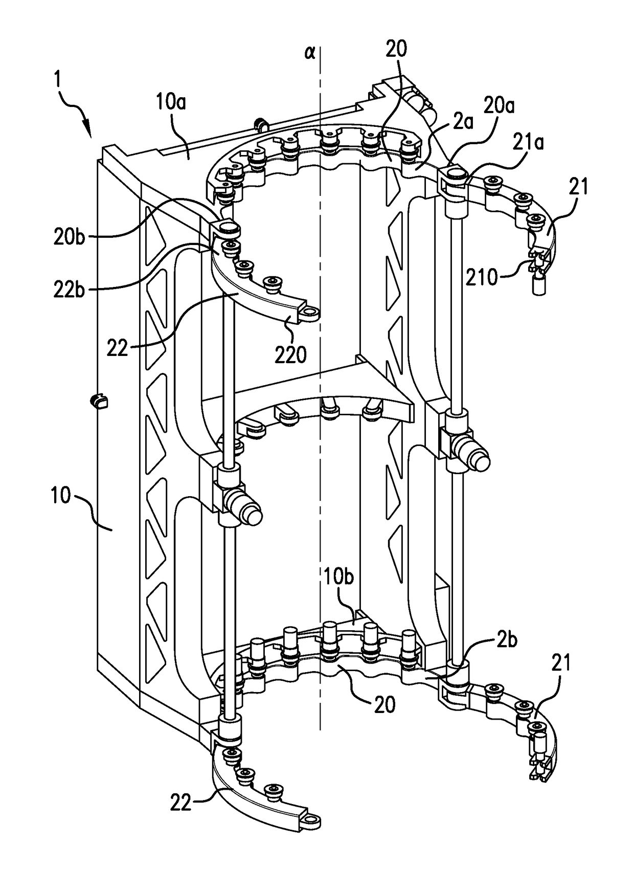
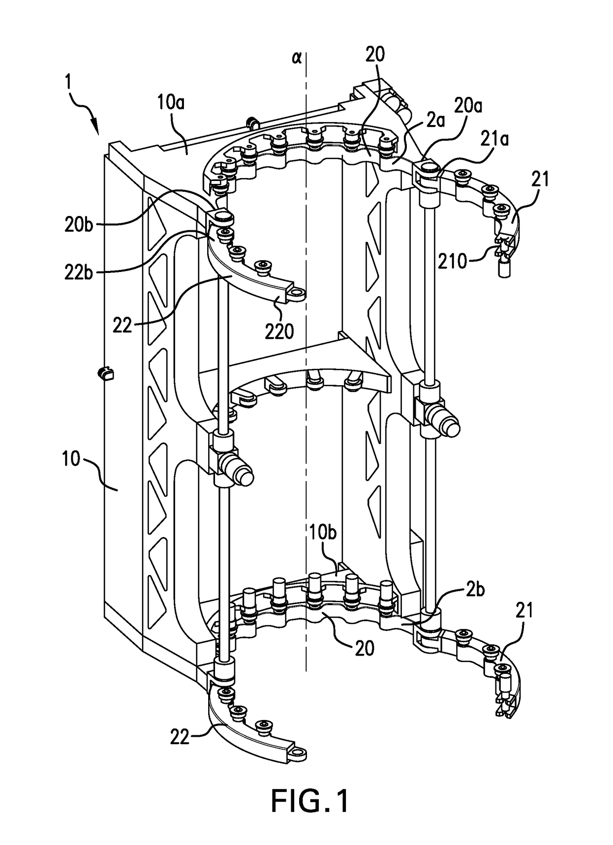
[0026]FIG. 1 shows an axon...


PUM


Abstract

A device for handling an artifact of substantially cylindrical shape, having a bed (10) and supporting means fixed to the bed (10) and connected to actuators. The supporting means being positioned along at least an arc of circumference lying in a plane orthogonal to the development axis α of the bed (10) and having rolling elements (3) adapted to support and handle an artifact, at least one of them being motorized. Each rolling element (3) is connected to one of a plurality of corresponding actuators operatively connected to each other and adapted to regulate a movement of the rolling elements (3) in response to forces exerted by the artifact on each rolling element (3), in such a way as to distribute the forces uniformly on each rolling element (3) to position one or more resultants of the forces in one or more points.

Description

TECHNICAL FIELD[0001]The present invention relates to the field of devices for handling artifacts.[0002]The present invention particularly relates to devices for handling artifacts according to the preamble of claim 1.PRIOR ART[0003]The handling of artifacts, and particularly large artifacts, is a common problem in the industry sector.[0004]Generally, in industrial applications, such artifacts are handled by means of articulated mechanical arms or automatized robots, however this being a solution that employs complicated control techniques also as regards alignment of components to be assembled.[0005]A solution to such problem provides structures, intended to receive the various components, which allow assembling both along an axis parallel to and an axis vertical to the ground plane.[0006]An example are “cradle”-like structures that provide supporting means, such as for example sliding blocks, to support the load of the artifact. Such sliding blocks are equipped with air tubes that...

Claims


Application Information

Patent Timeline
Patent Type & Authority Patents(United States)
IPC IPC(8): B66C3/14B23Q7/04B65G47/90B23Q3/06
CPCB66C3/14B23Q3/064B65G47/905B65G47/90B23Q7/04
Inventor TERZUOLO, PIERLUIGILIPPI, FABRIZIO
Owner IND COMETTO
Why Eureka
Try Eureka