
Piezoelectric actuator, piezoelectric vibration device, and portable terminal

a piezoelectric actuator and actuator technology, applied in the direction of mechanical vibration separation, mechanical pattern conversion, instruments, etc., can solve the problems of noise detection of vibration, quality degradation of piezoelectric actuators, and noise reduction of piezoelectric actuators, so as to reduce noise and reduce noise

Active Publication Date: 2018-05-29
KYOCERA CORP
View PDF14 Cites 8 Cited by
  • Summary
  • Abstract
  • Description
  • Claims
  • Application Information

AI Technical Summary

Benefits of technology

The invention provides a piezoelectric actuator with a shock-absorbing material that reduces vibration from the piezoelectric element. This reduces noise and prevents it from affecting the connection between components. As a result, devices that use the actuator and portable terminals have better quality and performance.

Problems solved by technology

Therefore, as a problem that exists in a conventional piezoelectric actuator, vibration of a piezoelectric element is transmitted even to a junction between a flexible substrate and an external circuit (connector junction) which is opposite to a junction between the flexible substrate and the piezoelectric element, and, the vibration is detected as noise.
Furthermore, a piezoelectric vibration device and a portable terminal which are equipped with the above-described piezoelectric actuator may suffer from quality degradation due to noise resulting from vibration of the piezoelectric element.

Method used


Image

  • Piezoelectric actuator, piezoelectric vibration device, and portable terminal
  • Piezoelectric actuator, piezoelectric vibration device, and portable terminal
  • Piezoelectric actuator, piezoelectric vibration device, and portable terminal

Examples


Embodiment Construction

[0026]An example of a piezoelectric actuator according to an embodiment of the invention will be described in detail with reference to drawings.

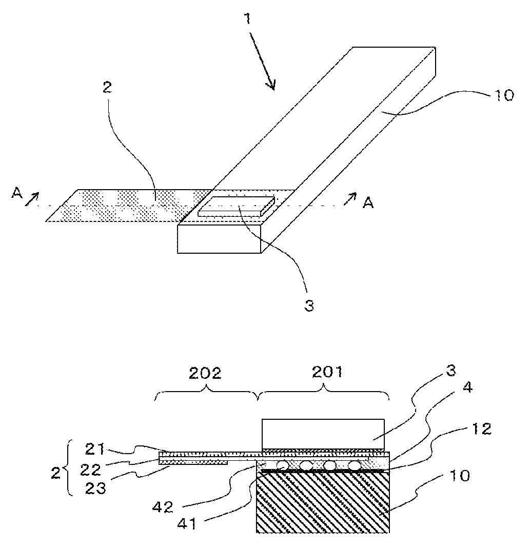
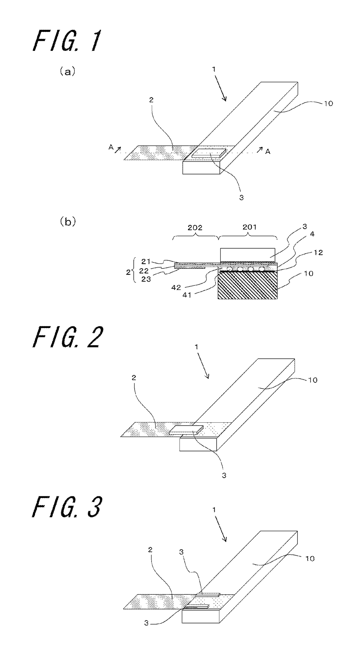
[0027]FIG. 1(a) is a schematic perspective view showing an example of a piezoelectric actuator according to an embodiment of the invention, and FIG. 1(b) is a schematic sectional view taken along the line A-A shown in FIG. 1(a).

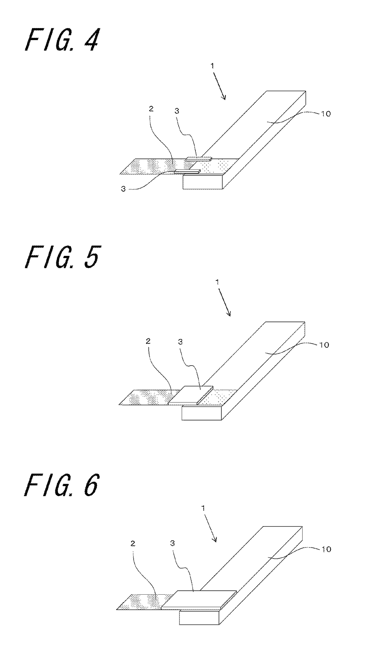
[0028]A piezoelectric actuator 1 of the present embodiment as shown in FIG. 1 comprises: a piezoelectric element 10 comprising a stacked body 11 composed of internal electrodes and piezoelectric layers which are laminated, and a surface electrode 12 disposed on one of main surfaces of the stacked body 11 so as to be electrically connected to the internal electrode; a flexible substrate 2 electrically connected to the surface electrode 12; and a shock-absorbing material 3 disposed on the flexible substrate 2. The shock-absorbing material 3, at least partly, is disposed on a first region 201 of the flexible substrate 2 ...


PUM


Abstract

A piezoelectric actuator which is capable of reduction of noise resulting from vibration of a piezoelectric element, a piezoelectric vibration device, and a portable terminal are provided. A piezoelectric actuator includes a piezoelectric element including a stacked body composed of internal electrodes and piezoelectric layers which are laminated, and a surface electrode disposed on one of main surfaces of the stacked body so as to be electrically connected to the internal electrodes; a flexible substrate electrically connected to the surface electrode; and a shock-absorbing material disposed on the flexible substrate. The shock-absorbing material, at least partly, is disposed on a first region of the flexible substrate which overlaps with the piezoelectric element.

Description

BACKGROUND OF THE INVENTION[0001]The present invention relates to a piezoelectric actuator which is suitable for use in a piezoelectric vibration device and a portable terminal, a piezoelectric vibration device, and a portable terminal.[0002]As piezoelectric actuators, there are known a construction employing a bimorph-type piezoelectric element obtained by forming a surface electrode on a surface of a stacked body composed of internal electrodes and piezoelectric layers which are laminated (refer to Japanese Unexamined Patent Publication JP-A 2002-10393), and a construction in which a piezoelectric element and a flexible substrate are joined to each other by an electrically-conductive connecting member, so that a surface electrode of the piezoelectric element and a wiring conductor of the flexible substrate are electrically connected to each other (refer to Japanese Unexamined Patent Publication JP-A 6-14396 (1994).BRIEF SUMMARY OF THE INVENTION[0003]A flexible substrate is general...

Claims


Application Information

Patent Timeline
Patent Type & Authority Patents(United States)
IPC IPC(8): H01L41/09H01L41/047G06F3/01H01L41/053H01L41/29G10K9/122H04M1/02B06B1/06H01L41/083
CPCH01L41/0533B06B1/0603B06B1/0611B06B1/0681G06F3/016G10K9/122H01L41/0475H01L41/09H01L41/0973H01L41/29H04M1/026H01L41/0472H04M2250/12H01L41/083H10N30/875H10N30/883H10N30/2047H10N30/50H10N30/06H10N30/20H10N30/872
Inventor MORI
Owner KYOCERA CORP
Learn More