Eureka AIR delivers breakthrough ideas for toughest innovation challenges, trusted by R&D personnel around the world.

Electronic device and method of initializing controller of electronic device

a technology of electronic devices and controllers, applied in the field of electronic devices, can solve the problems of bringing the electronic device into a runaway state, the occurrence the re-initialization of the runaway state, and the repetition of the re-initialization from the runaway state, so as to shorten the time required and reduce the voltage of the secondary battery

Active Publication Date: 2018-06-05
SEIKO EPSON CORP
View PDF7 Cites 0 Cited by
  • Summary
  • Abstract
  • Description
  • Claims
  • Application Information

AI Technical Summary

Benefits of technology

[0006]An advantage of some aspects of the invention is to provide a technique which prevents continuation of a runaway state while avoiding a system from being inadvertently initialized due to a temporarily decreased voltage in an electronic device which uses a secondary battery.
[0008]According to the electronic device, even when the voltage of the secondary battery becomes equal to or lower than the first threshold voltage since any one of one or other multiple circuits is driven, if the time length of the period while the voltage of the secondary battery falls below the first threshold voltage is shorter than the predetermined period of time, the initializing signal is not output. Therefore, even when the voltage of the secondary battery temporarily falls below the first threshold voltage since any one of one or other multiple circuits is driven, there is no possibility of inadvertent initializing. In addition, in the electronic device according to the aspect of the invention, until the voltage of the secondary battery becomes equal to or higher than the second threshold voltage, the processing for outputting the initializing signal at the predetermined timing is continuously performed. Therefore, it is possible to prevent continuation of a runaway state.
[0011]In a preferred aspect of the invention, the controller stops driving of a predetermined circuit within one or other multiple circuits, in response to a starting point in which the voltage of the secondary battery falls below the first threshold voltage. According this aspect, since power consumption is suppressed after the voltage of the secondary battery falls below the first threshold voltage, it is possible to shorten the time required until a normal operation is restored. In another preferred aspect of the invention, the controller stops driving of a predetermined circuit within one or other multiple circuits, in response to a starting point in which the voltage of the secondary battery falls below a third threshold voltage which is set to be higher than the first threshold voltage. According to this aspect, it is possible to maintain a normal operation state for a long time by lengthening the time required until the voltage of the secondary battery falls below the first threshold voltage.
[0013]In another preferred aspect of the invention, more preferably, the predetermined period of time is set to be shorter than a period of time during which the voltage of the secondary battery decreases from the first threshold voltage to the operation-guaranteed voltage, when the electronic device is operated in a state where power is not supplied to the secondary battery. The reason is to reliably prevent a runaway state of the controller which is caused by a decreased voltage of the secondary battery.
[0014]In another preferred aspect of the invention, the electronic device further includes a watchdog timer that initializes a system in response to a starting point where a predetermined time is measured, and the initializing unit resets time measurement of the watchdog timer at predetermined timing when the voltage of the secondary battery is higher than the first threshold voltage, whereas the initializing unit suspends the resetting for the time measurement of the watchdog timer, when a state where the voltage of the secondary battery is equal to or lower than the first threshold voltage continues for the predetermined period of time or longer. The watchdog timer is often disposed in the electronic device such as electronic timepieces in order to avoid a runaway state of software. In this case, by using the watchdog timer disposed in the electronic device, it is possible to prevent continuation of a runaway state while avoiding a system from being inadvertently initialized due to a temporarily decreased voltage in the electronic device which uses the secondary battery.
[0015]In another preferred aspect of the invention, the electronic device includes a voltage generator and a switch which are interposed and inserted in parallel between the former of high-potential side and low-potential side power supply lines for supplying power to the one or other multiple circuits and the controller, and a high-potential side terminal of the secondary battery, and the initializing unit turns off the switch in response to a starting point where the outputting of the initializing signal starts, the initializing unit may turn on the switch in response to a starting point where the outputting of the initializing signal stops, and compares the voltage of the secondary battery with the second threshold voltage, in such a way that a potential difference between the high-potential side and the low-potential side power supply lines is regarded as the voltage of the secondary battery. Specific examples of the voltage generator include diodes or resistors, and specific examples of the switch include transistor switches. According to this aspect, a potential difference between the high-potential side power supply line and the low-potential side power supply line coincides with the voltage of the high-potential side terminal of the secondary battery in a state where the switch is turned on, and coincides with a voltage obtained by adding a voltage generated by the voltage generator (voltage corresponding to voltage decreased due to a fact that a current flows into the secondary battery through a diode) to the voltage of the high-potential side terminal of the secondary battery in a state where the switch is turned off. That is, according to this aspect, the second threshold voltage and a comparison-target voltage are increased by the voltage generator. Therefore, it is possible to shorten the time required until a normal operation is restored.

Problems solved by technology

If the power supply voltage in this type of electronic device falls below a lower limit value of a voltage which guarantees a normal operation (hereinafter, referred to as an operation-guaranteed voltage) for a controller such as a Central Processing Unit (CPU), a normal control cannot be performed, thereby bringing the electronic device into a runaway state in some cases.
Even when charging for the power source and power consumption are performed in parallel, if a state continues where a charging current falls below a consumed current, there is also a possibility that the electronic device may be brought into the runaway state.
In addition, when the charging for the power source and the power consumption are performed in parallel, the charging and the power consumption cause the power supply voltage to pulsate over the operation-guaranteed voltage, thereby causing a possibility that the occurrence of the runaway state and restoring from the runaway state may be repeated.
However, according to the technique disclosed in JP-A-2006-153669, when the power supply voltage falls below the set voltage due to a temporarily decreased voltage which is caused by a heavy load, the initializing signal is output, thereby causing a possibility that the system may be inadvertently initialized.
For example, when the technique disclosed in JP-A-2006-153669 is applied to an alarm-installed solar timepiece, there is a disadvantage in that the system is initialized due to a temporarily decreased voltage which is caused by alarm sounding.

Method used


Image

  • Electronic device and method of initializing controller of electronic device
  • Electronic device and method of initializing controller of electronic device
  • Electronic device and method of initializing controller of electronic device

Examples


first embodiment

A: First Embodiment

A-1: Configuration

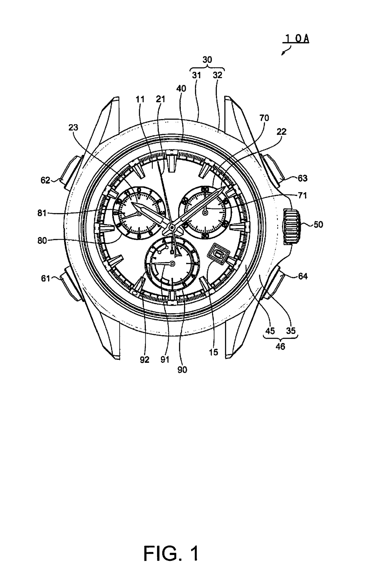
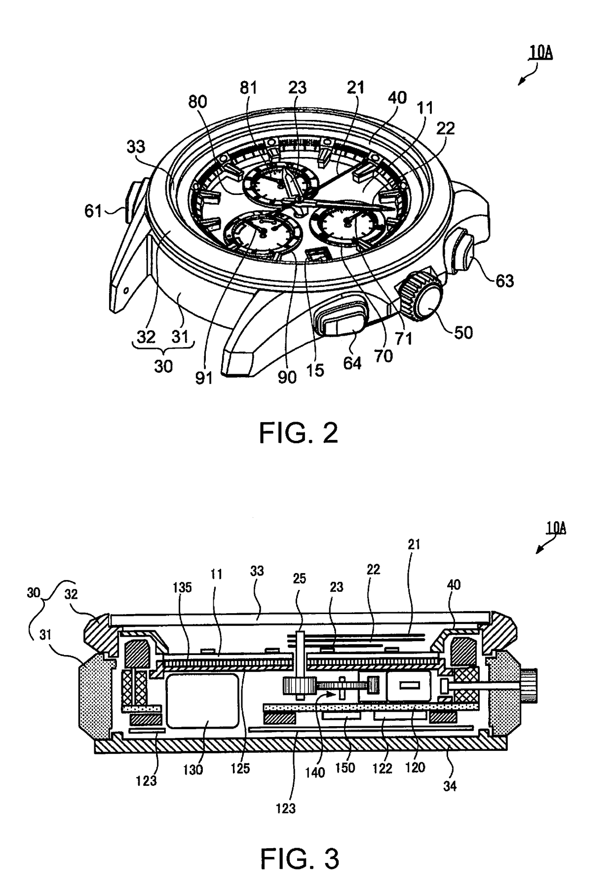
[0028]FIG. 1 is a plan view illustrating an outer shape of an electronic timepiece 10A according to a first embodiment of an electronic device according to the invention. FIG. 2 is a perspective view illustrating the outer shape of the electronic timepiece 10A. The electronic timepiece 10A is a multi-functional alarm-installed solar timepiece provided with an alarm sounding function and a stopwatch function. As illustrated in FIGS. 1 to 3, the electronic timepiece 10A includes an exterior case 30, a cover glass 33, and a case back 34. The exterior case 30 is configured so that a ceramic-made bezel 32 is fitted to a metal-made and cylindrical case 31. A disc-shaped dial 11 serving as a time display section is arranged on an inner peripheral side of the bezel 32 via a plastic-made and ring-shaped dial ring 40.

[0029]The dial 11 includes indicating hands 21, 22, and 23. The dial 11 has a circular first small window 70 and an indicating hand 71 in the...

second embodiment

B: Second Embodiment

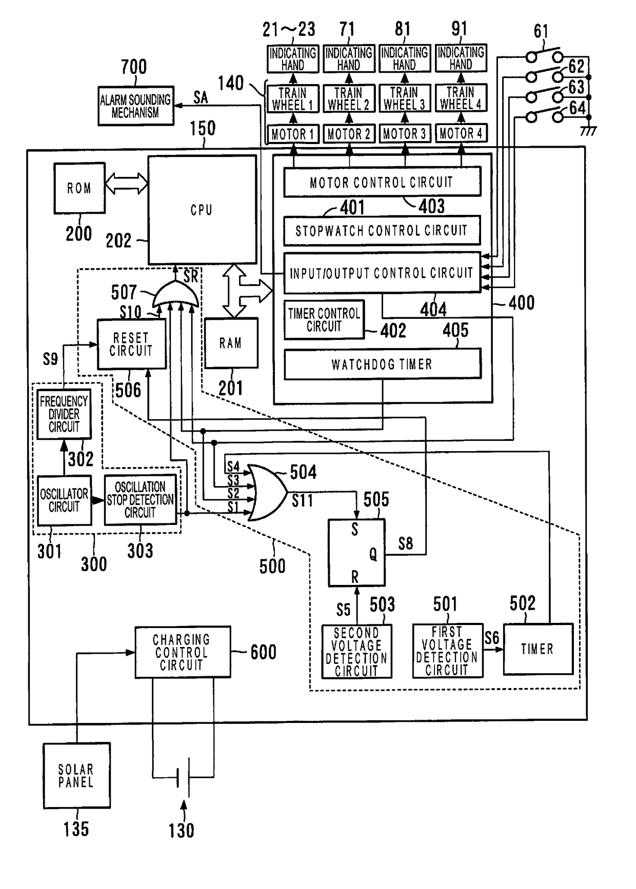
[0063]FIG. 7 is a block diagram illustrating an example of an electrical configuration of an electronic timepiece 10B according to a second embodiment of the electronic device according to the invention, that is, a configuration example of a control display unit 150 belonging to the electronic timepiece 10B. The peripheral circuit 400 of the electronic timepiece 10B is realized by a software module, and the first voltage detection circuit 501 is also realized by a software module. This point is different from that of the electronic timepiece 10A. According to the embodiment, as illustrated in FIG. 7, in the electronic timepiece 10B, a counter ct functioning as the timer 502 is realized by a portion of the RAM 201.

[0064]Next, similarly to the case of the first embodiment, an operation performed by the CPU 202 of the electronic timepiece 10B will be described by citing the following case as an example. At times 0 to t3 and after time t7, the solar panel 135 is expo...

modification example

C: Modification Example

[0069]Hitherto, the first and second embodiments according to the invention have been described. However, as a matter of course, modification examples to be described below may be added to the embodiments.

[0070](1) A function of the electronic timepiece 10A (or the electronic timepiece 10B) may be partially stopped in response to a starting point where the voltage VDD of the secondary battery 130 falls below the first threshold voltage V1. Specifically, a function which needs a large amount of power consumption such as the alarm sounding function in the above-described embodiments is stopped in response to the starting point where the voltage VDD of the secondary battery 130 falls below the first threshold voltage V1. If the function which needs a large amount of power consumption is operated in a state where the voltage VDD of the secondary battery 130 falls below the first threshold voltage V1, the time required until the power supply voltage VDD of the seco...


PUM


Abstract

An electronic device that has a secondary battery and a controller which receives power supply from the secondary battery so as to perform a drive control on one or other multiple circuits driven by receiving the power supply from the secondary battery includes an initializing unit that starts processing for outputting an initializing signal to instruct the controller to perform initializing at predetermined timing, in response to a starting point in which a voltage of the secondary battery becomes equal to or lower than a first threshold voltage which is set to be higher than an operation-guaranteed voltage of the controller and a lower state thereof continues for a predetermined period of time.

Description

BACKGROUND[0001]1. Technical Field[0002]The present invention relates to an electronic device which uses a secondary battery.[0003]2. Related Art[0004]For example, an electronic device which uses a secondary battery as a power source, such as an electronic timepiece including a solar cell (hereinafter, referred to as a “solar timepiece”), has been generally and widely used. If this type of electronic device is driven in a state where the electronic device is left in a dark place without charging the secondary battery, a power supply voltage is gradually reduced. If the power supply voltage in this type of electronic device falls below a lower limit value of a voltage which guarantees a normal operation (hereinafter, referred to as an operation-guaranteed voltage) for a controller such as a Central Processing Unit (CPU), a normal control cannot be performed, thereby bringing the electronic device into a runaway state in some cases. Even when charging for the power source and power co...

Claims


Application Information

Patent Timeline
Patent Type & Authority Patents(United States)
IPC IPC(8): G06F1/24H03K17/22G06F1/26G04G19/10G04C10/02
CPCG06F1/24G04G19/10H03K17/22G06F1/263G04C10/02
Inventor KAWAGUCHI, TAKASHINAKAMIYA, SHINJI
Owner SEIKO EPSON CORP
Why Eureka
Eureka Blog
Learn More