Aerosol generating device with heater assembly

a technology of a heater and aerosol, which is applied in the direction of inhalators, tobacco,horticulture, etc., can solve the problems of difficult to efficiently heat the aerosol-forming substrate, and achieve the effects of reducing the external diameter of the device, and reducing the difficulty of inhalation

Active Publication Date: 2018-06-19
PHILIP MORRIS PROD SA
View PDF46 Cites 43 Cited by
  • Summary
  • Abstract
  • Description
  • Claims
  • Application Information

AI Technical Summary

Benefits of technology

[0006]The use of a movable heating element within the aerosol-forming substrate means that efficient heating can be accomplished with minimal heat losses. The use of a heating element within the aerosol-forming substrate also means that the external diameter of the device can be minimized because insulation is not necessary as compared to externally positioned heater elements. The distance that the heating element is required to move within the aerosol-forming substrate can be made very small, and is smaller than would be required to move between corresponding portions of the substrate if the heating element were positioned externally of the aerosol-forming substrate.
[0007]The positioning mechanism may be coupled to the housing. Preferably, the positioning mechanism further comprises an engagement mechanism. The engagement mechanism is configured to move the heating element towards or away from an interior surface of the internal cavity. More preferably, the engagement mechanism is configured to move the heating element into or out of contact with the interior surfaces of the aerosol-forming substrate. This allows for efficient thermal transfer from the heating element to the aerosol-forming substrate during heating. The engagement mechanism also allows for smooth movement between heating positions when the heating element is not activated, and for easy insertion and removal of the aerosol-forming substrate.
[0008]The heating element may be placed in direct thermal contact with the aerosol-forming substrate or may be positioned close to the substrate without contacting it. Alternatively, the heating element may be in indirect contact with the aerosol-forming substrate. For example, a conductive layer may be provided between the heating element and the aerosol-forming substrate. The conductive layer may be a foil layer that conducts heat from the heating element to the aerosol-forming substrate but prevents damage to the aerosol-forming substrate caused by movement of the heating element. It may also spread the heat contact area or contact force so as not to damage the aerosol-forming substrate.

Problems solved by technology

In a device in which a heating element is moved relative to an aerosol-forming substrate to heat different portions, it has been difficult to efficiently heat the aerosol-forming substrate.

Method used


Image

  • Aerosol generating device with heater assembly
  • Aerosol generating device with heater assembly
  • Aerosol generating device with heater assembly

Examples


Embodiment Construction

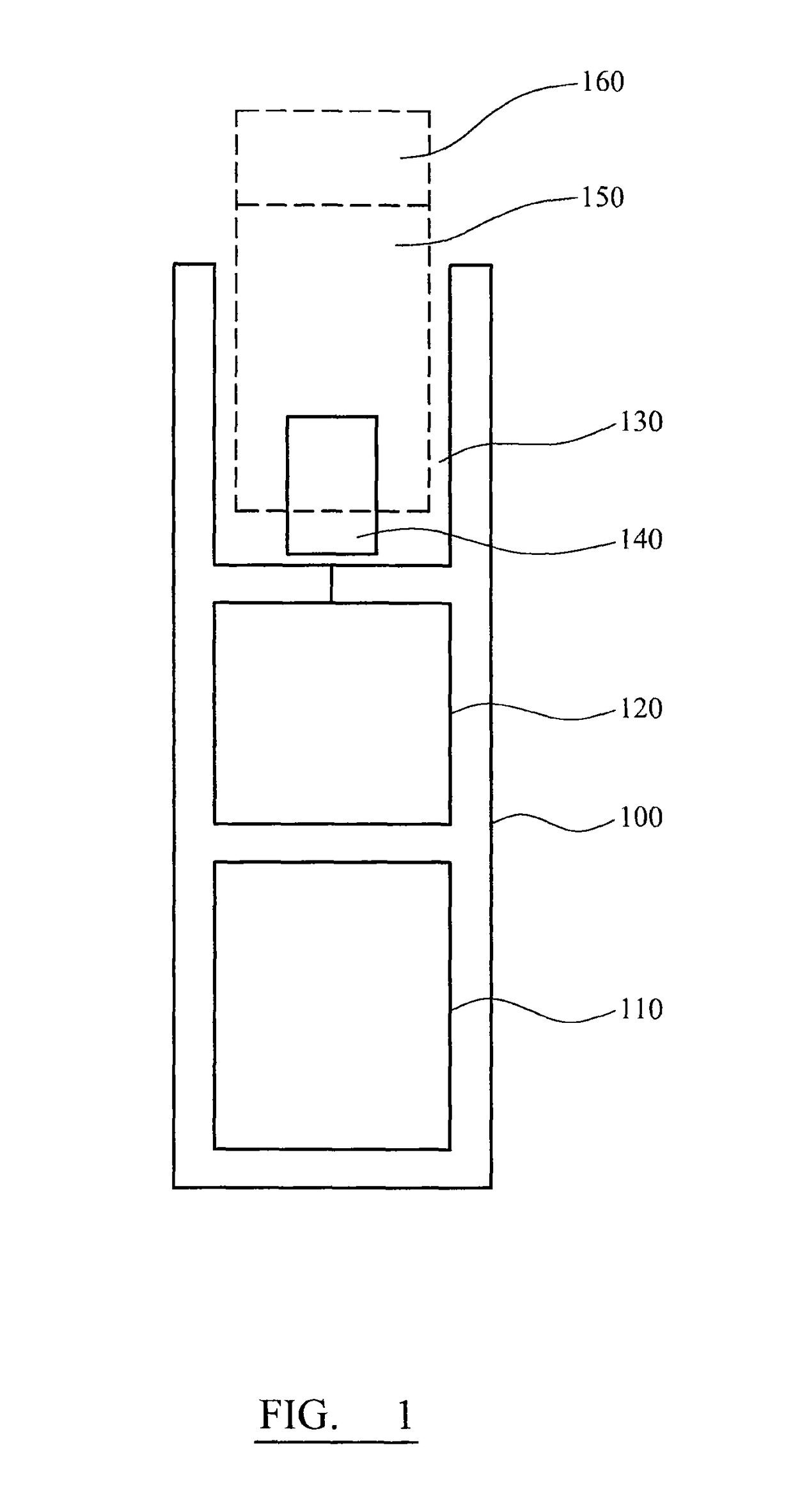
[0054]FIG. 1 is a schematic illustration of an electrically powered smoking device. The device comprises a housing 100 containing a battery 110, control electronics 120 and a heater 140, together with a positioning mechanism for moving the heater. The heater 140 is positioned within a socket 130 configured to receive a consumable element 150 containing an aerosol-forming substrate. The consumable element also comprises a filter element 160 through which a user inhales aerosol formed in the device. The aerosol-forming substrate is heated by the heater and releases vaporized flavor compounds. The vapors nucleate to form an aerosol, which is drawn through the filter 160 by a user inhalation.

[0055]The heater is configured and controlled to provide short bursts of heat on a per-puff basis. The heater heats a new portion of the aerosol-forming substrate for each puff, to ensure that the desired amount and desired characteristics of aerosol are achieved.

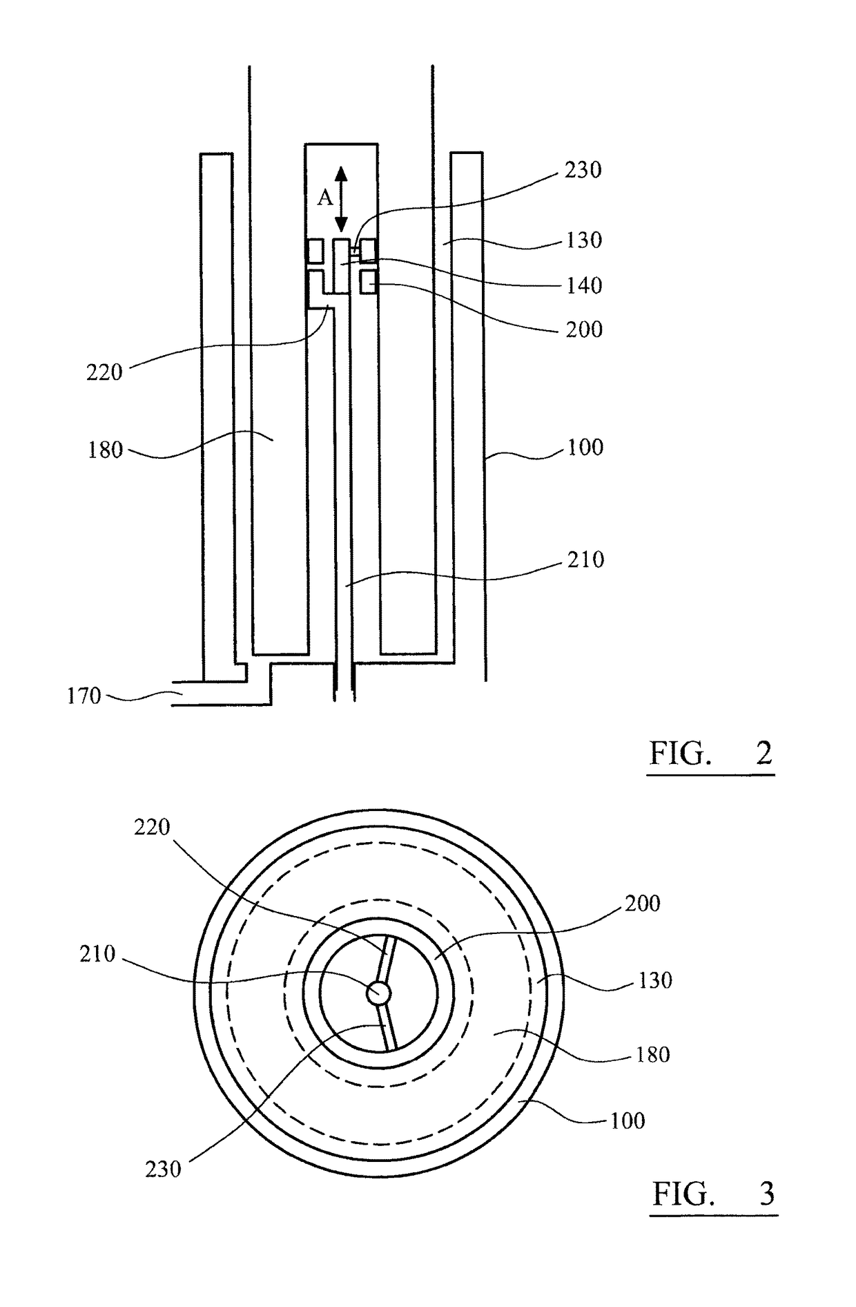
[0056]FIGS. 2 and 3 show the heater ...


PUM


Abstract

An aerosol generating device is provided, including a housing configured to receive an aerosol-forming substrate having an internal cavity; a heating element configured to be received within the internal cavity of the substrate, and a positioning mechanism coupled to the heating element and to the housing being configured to move the heating element between a plurality of heating positions within the cavity. There is also provided an aerosol generating device including a housing configured to receive an aerosol-forming substrate, a heating element configured to heat a portion of the substrate, and a positioning mechanism configured to move the heating element from a first position next to a first portion of the substrate, to a second position remote from the substrate, and then to a third position next to a second portion of the substrate.

Description

CROSS REFERENCE TO RELATED APPLICATION[0001]This application is a national phase application based on PCT / EP2012 / 071083, filed on Oct. 24, 2012.TECHNICAL FIELD[0002]The present invention relates to an aerosol generating device with an improved heater assembly. The invention finds particular application in an electrically operated smoking system as a heater assembly for heating an aerosol-forming substrate.DESCRIPTION OF THE RELATED ART[0003]Patent application U.S. Pat. No. 5,269,327 discloses an electrical smoking article comprising a plurality of charges of tobacco flavor medium which are heated sequentially to provide individual puffs. The sequential heating can be provided either by a plurality of individually activated heater elements or portions of a heater element, or by a single movable heater element.[0004]It would be advantageous to provide an aerosol generating system that improves on these known schemes for heating an aerosol-forming substrate by providing a more develope...

Claims


Application Information

Patent Timeline
Patent Type & Authority Patents(United States)
IPC IPC(8): A01G13/06H05B3/58A24F1/22A24F47/00A24F40/20A24F40/46
CPCA24F47/008A24F40/46A24F40/20A24F40/40A24F40/50A24F40/10A24B15/167A61M15/06A61M11/042
Inventor RUSCIO, DANIGREIM, OLIVIERPLOJOUX, JULIEN
Owner PHILIP MORRIS PROD SA
Why Eureka
Try Eureka