Current decay control in switched reluctance motor

a technology of switched reluctance and current decay, which is applied in the direction of motor/generator/converter stopper, electronic commutator, dynamo-electric converter control, etc., can solve the problems of aggravated noise problem, motor noise, and divide the decay interval into two segments, so as to reduce noise in srms, lessen motor noise, and control the slope of the decay current curve

Inactive Publication Date: 2000-02-15
NIDEC MOTOR CORP
View PDF53 Cites 14 Cited by
  • Summary
  • Abstract
  • Description
  • Claims
  • Application Information

AI Technical Summary

Benefits of technology

Among the several objects of the present invention may be noted the provision of a control circuit for controlling the residual or tail current decay in a motor winding; the provision of such a control circuit which controls tail current decay so as to lessen motor noise at least 10 dBA from current noise levels; the provision of such a control circuit which integrates both hard chopping and soft chopping current decay control techniques; the provision of such a current control circuit which provides both types of chopping using but a single gate drive; the provision of such a control circuit which is usable with both 2-phase and 3-phase SRM's such as a 12-6, 2-phase SRM and a 6-4, 3-phase SRM; the provision of such a control circuit which is readily incorporated into a PWM type controller for controlling overall average voltage applied to the respective phases of a SRM; the provision of such a control circuit which reverses the pulse width characteristics of a PWM signal used to control current flow when a winding phase is inactive thereby to help slow the rate at which current goes to zero while the phase is inactive; the provision of such a control circuit employing two sets of switches one set of which is either act

Problems solved by technology

One problem with operating these motors is noise caused by the recovery of current in the motor phase windings as each phase is switched at the end of its cycle.
The result of this ringing or transfer of forces into the motor frame causes noise, and this noise is on the order of 50 dBa.
However, it is a drawback of these decay control circuits that they

Method used


Image

  • Current decay control in switched reluctance motor
  • Current decay control in switched reluctance motor
  • Current decay control in switched reluctance motor

Examples


Embodiment Construction

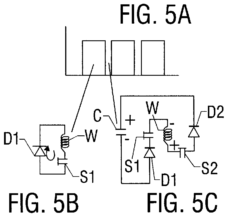
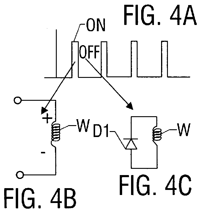
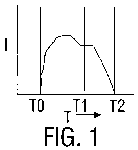
Referring to the drawings, a switched reluctance motor (not shown) is a motor having 1,2,3,4, or 5 phases and is typically a multiple pole motor. Examples of such motors are a 12-6, 2-phase motor, or a 6-4, 3-phase motor. In operation, each respective phase is energized and de-energized in a sequential manner. The length of time each phase is active is based on various operating parameters and various control schemes have been implemented to determine when switching should occur from one phase to the next. During the interval a phase is active a phase winding W of that phase is supplied current. An idealized current profile for the winding is shown in FIG. 1. As depicted in the graph, power to the phase (current to the winding) commences at time T.sub.0. Current is then applied to winding W until a time T.sub.1 at which time the particular phase is deactivated or de-energized. As indicated in FIG. 1, there is a significant amount of energy in winding W at this time, and this residua...


PUM


Abstract

A control circuit (10) for controlling the residual or tail current decay in a single phase or polyphase SRM winding when a phase is switched from active to inactive. A Hall-effect type sensor (30) senses rotor position of the SRM. Current flows through a winding (W) of the motor when the motor phase winding is active; and, current flow into the winding decays to zero when the phase becomes inactive. Semiconductor switches (22) direct current flow into the winding when the phase is active and then redirect residual energy in the winding between an energy recovery circuit and an energy dissipation circuit when the phase becomes inactive. A PWM signal generator (44) provides PWM operating signals to the switches to control current flow first into the winding and then between the recovery and dissipation circuits. A control module (42), or microprocessor (52) with a PWM output, is responsive to rotor position information for controlling operation of the PWM signal generator. The signal generator provides PWM signals having one set of signal characteristics when there is current flow to the winding and a different set of characteristics when there is not. This produces alternate intervals of zero voltage and forced commutation residual current decay while the phase is inactive. During the decay interval, both the PWM frequency and pulse duty cycle are variable to produce a current decay scheme which eliminates ringing and motor noise.

Description

BACKGROUND OF THE INVENTIONThis invention relates to switched reluctance (SRM) motors and, more particularly, to a current decay control circuit for such motors.Switched reluctance, or SRM motors are well-known in the art. One problem with operating these motors is noise caused by the recovery of current in the motor phase windings as each phase is switched at the end of its cycle. It will be understood that the current representing the energy input of a particular phase is supplied to the phase windings during that phase's active portion of a switching cycle. As the motor is switched from one phase to another, the residual energy in the deactivated winding decays off. This energy typically represents approximately thirty percent (30% ) of the energy supplied to the phase winding during its active period and is referred to as the "tail decay energy". Since the phase winding is an inductive element, it attempts to maintain the current flow through the winding; even though the energy ...

Claims


Application Information

Patent Timeline
IPC IPC(8): H02P25/08H02P25/02B60C15/02
CPCH02P25/082H02P25/0925
Inventor HORST, GARY E.
Owner NIDEC MOTOR CORP
Why Eureka
Try Eureka