
A low-center, high-power, high-speed, high-voltage motor assembly method

A technology of high-voltage motors and assembly methods, applied in electromechanical devices, manufacturing motor generators, electrical components, etc., can solve the problems of motor vibration, bearing temperature rise, and motor noise that cannot reach a high level, and cannot fully exert the excellent performance of the motor. The service life of the motor and other issues can be improved to achieve the effect of increasing the service life, reducing the temperature rise of the bearing and improving the wear resistance

Active Publication Date: 2020-06-19
SEC ELECTRIC MACHINERY
View PDF1 Cites 0 Cited by
  • Summary
  • Abstract
  • Description
  • Claims
  • Application Information

AI Technical Summary

Problems solved by technology

[0002] As an international emerging technology, the new low-center, high-power, high-speed and high-voltage motor is rapidly and widely used in various industries. For example, it can be used to drive water pumps, compressors, cutting machine tools and other general machinery. It can serve mines , metallurgy, petrochemical, power station, papermaking or building materials and other industries. Compared with Y, YKS, YKK series high-voltage motors of the same power, this type of motor has the characteristics of small size, high power density and high cost performance. The precision requirements are very high. According to the conventional assembly technology, the conventional indicators such as motor vibration, bearing temperature rise and motor noise cannot reach a high level. Low-precision assembly seriously affects the service life of the motor and cannot give full play to the performance of the motor. excellent performance

Method used


Image

  • A low-center, high-power, high-speed, high-voltage motor assembly method
  • A low-center, high-power, high-speed, high-voltage motor assembly method
  • A low-center, high-power, high-speed, high-voltage motor assembly method

Examples


Embodiment Construction

[0037] The following will clearly and completely describe the technical solutions in the embodiments of the present invention with reference to the accompanying drawings in the embodiments of the present invention. Obviously, the described embodiments are only some, not all, embodiments of the present invention. Based on the embodiments of the present invention, all other embodiments obtained by persons of ordinary skill in the art without making creative efforts belong to the protection scope of the present invention.

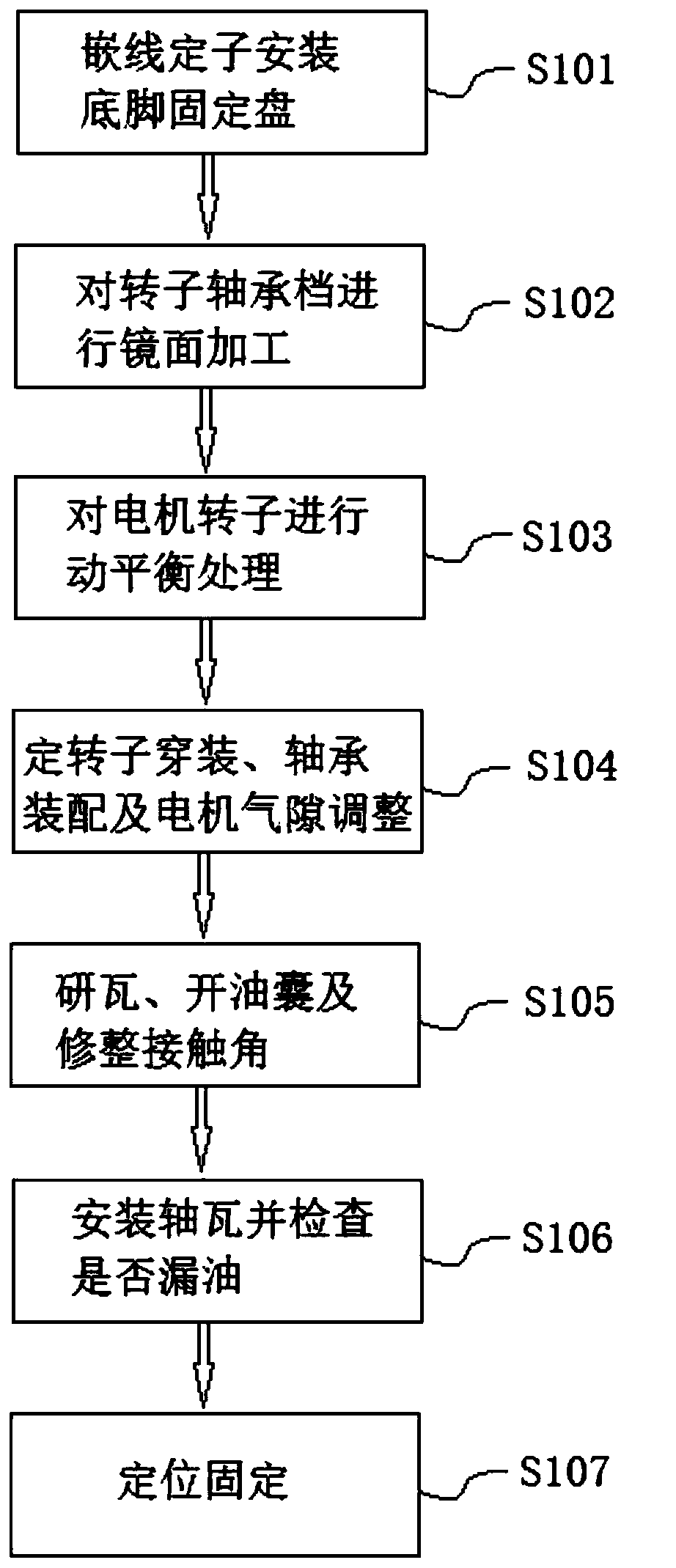
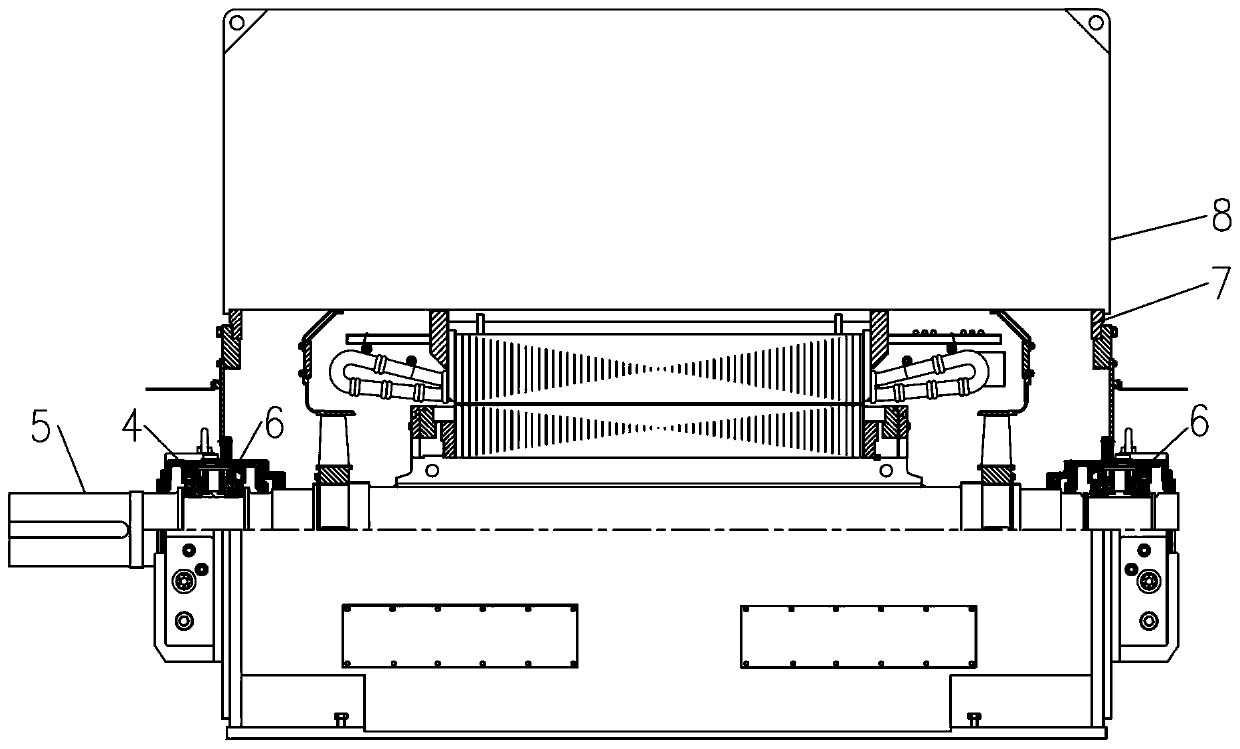
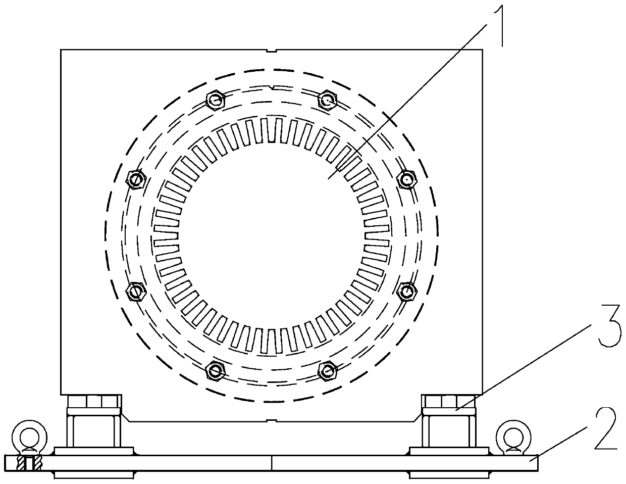
[0038] see Figure 1-5 , the present invention provides a technical solution: a method for assembling a low-center, high-power, high-speed, high-voltage motor, comprising the following steps:

[0039] S101: if image 3 As shown, install the foot fixing plate 2 under the foot plate 3 of the embedded wire stator 1;

[0040] Specifically, wire-embedded stator 1 is obtained by embedding wires on the stator core, and foot fixing plate 2 is installed under the foo...


PUM


Abstract

The invention relates to the field of motor assembly, in particular to an assembly method of a low-center, large-power, high-speed and high-voltage motor. The assembly method comprises the following steps of arranging a bottom leg fixing disc below a bottom leg plate of a wire embedment stator; performing mirror processing on a rotor bearing guard; performing dynamic balancing on a motor rotor; disassembling the bottom leg fixing disc, enabling the wire embedment stator to penetrate through the motor rotor, installing sliding bearings at two ends, measuring and adjusting an air gap value between the wire embedment stator and the rotor, and effectively locking the wire embedment stator; disassembling shaft tiles of the sliding bearings at the two ends, and researching the shaft tiles; opening oil bags in an oil inlet surface and an oil outlet surface of a lower tile, and trimming a contact angle between the shaft tiles and shaft necks; assembling the shaft tiles, and detecting whether oil is leaked or not; completing wiring operation outside the motor, arranging a sealing piece and a cooler, performing test, and performing spot welding and fixing on a fixed screw and a positioning pin after test is qualified. By the assembly method, the motor vibration can be reduced, the temperature rising of the bearing is reduced, the motor noise is reduced, and the service lifetime of the motor is prolonged.

Description

technical field [0001] The invention relates to the field of motor assembly, and the specific field is an assembly method of a low-center, high-power, high-speed, high-voltage motor. Background technique [0002] As an international emerging technology, the new low-center, high-power, high-speed and high-voltage motor is rapidly and widely used in various industries. For example, it can be used to drive water pumps, compressors, cutting machine tools and other general machinery. It can serve mines , metallurgy, petrochemical, power station, papermaking or building materials and other industries. Compared with Y, YKS, YKK series high-voltage motors of the same power, this type of motor has the characteristics of small size, high power density and high cost performance. The precision requirements are very high. According to the conventional assembly technology, the conventional indicators such as motor vibration, bearing temperature rise and motor noise cannot reach a high lev...

Claims


Application Information

Patent Timeline
Patent Type & Authority Patents(China)
IPC IPC(8): H02K15/00
CPCH02K15/00
Inventor 柳传友陈晓王恩会王浩王建裕
Owner SEC ELECTRIC MACHINERY
Learn More