Motor controller

a motor controller and controller technology, applied in the direction of electronic commutators, dc motor speed/torque control, dc motor rotation control, etc., can solve the problems of mechanical noise, difficult to design such driving methods, complicated detection methods, etc., and achieve the effect of reducing motor nois

Active Publication Date: 2022-03-24
GLOBAL MIXED MODE TECH
View PDF0 Cites 0 Cited by
  • Summary
  • Abstract
  • Description
  • Claims
  • Application Information

AI Technical Summary

Benefits of technology

[0004]According to one embodiment of the present invention, a motor controller which is capable of reducing the motor noise by detecting the zero point of the motor current is provided. The motor controller is used for driving a motor, where the motor has a motor coil. The motor coil has a first terminal and a second terminal. The motor controller comprises a switch circuit, a pre-driver, a phase detecting unit, a control unit, a comparator, a first resistor, and a second resistor. The switch circuit is coupled to a terminal VCC and a terminal S. The first resistor is coupled to the terminal S and a terminal GND, where the terminal S may be coupled to a sensing pin. The switch circuit includes a first transistor, a second transistor, a third transistor, and a fourth transistor for supplying a motor current to the motor coil. The first transistor is coupled to the terminal VCC and the first terminal while the second transistor is coupled to the first terminal and the terminal S. The third transistor is coupled to the terminal VCC and the second terminal while the fourth transistor is coupled to the second terminal and the terminal S. Moreover, the switch circuit is an H-bridge circuit. Each of the first transistor and the third transistor is an upper-side switch while each of the second transistor and the fourth transistor is a lower-side switch. The first transistor may be a first upper-side switch. The second transistor may be a first lower-side switch. The third transistor may be a second upper-side switch. The fourth transistor may be a second lower-side switch. The phase detecting unit generates a phase signal to the control unit, so as to inform the control unit to switch phases. The control unit receives the phase signal and a detecting signal for generating a control signal to the pre-driver. Based on the control signal, the pre-driver generates a plurality of driving signals to control the switch circuit.

Problems solved by technology

However, due to the effect of the back electromotive force during the rotation of the motor, the motor current IL left at the time point of phase switching will result in the mechanical noise.
However, the disadvantage of the P-type pulse width modulation mode is that it is not easy to design such driving method.
However, the disadvantage of the N-type pulse width modulation mode is that when the zero point of the motor current IL is detected at the time point T2, the voltage of the terminal VCC is compared for determining the zero point of the motor current IL, such that the detection method is complicated.
Therefore, it has become an important issue to make good use of the advantages of the two driving modes.

Method used


Image

  • Motor controller
  • Motor controller
  • Motor controller

Examples


Embodiment Construction

[0013]Preferred embodiments according to the present invention will be described in detail with reference to the drawings.

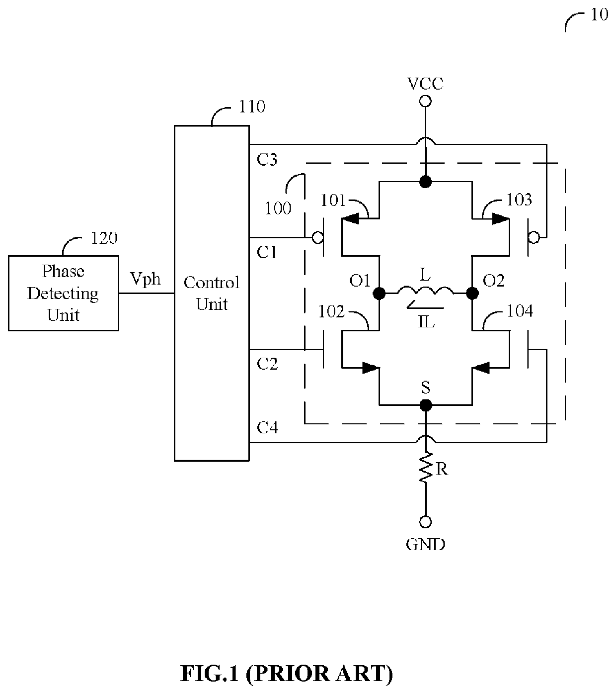
[0014]FIG. 4 is a circuit diagram showing a motor controller according to one embodiment of the present invention. A motor controller 20 is used for driving a motor, where the motor has a motor coil L. The motor coil L has a first terminal O1 and a second terminal O2. The motor controller 20 comprises a switch circuit 200, a pre-driver 210, a phase detecting unit 220, a control unit 230, a comparator 240, a first resistor R1, and a second resistor R2. The switch circuit 200 is coupled to a terminal VCC and a terminal S. The first resistor R1 is coupled to the terminal S and a terminal GND, where the terminal S may be coupled to a sensing pin. The switch circuit 200 includes a first transistor 201, a second transistor 202, a third transistor 203, and a fourth transistor 204 for supplying a motor current IL to the motor coil L. The first transistor 201 is coupled t...


PUM


Abstract

A motor controller configured to reduce the motor noise by detecting the zero point of the motor current is disclosed. The motor controller comprises a switch circuit, a pre-driver, a phase detecting unit, a control unit, a comparator, a first resistor, and a second resistor. The switch circuit is an H-bridge circuit. The switch circuit includes a first upper-side switch, a second upper-side switch, a first lower-side switch, and a second lower-side switch. When the motor controller performs the last pulse width modulation driving with respect to the first lower-side switch before phase switching, the second upper-side switch is turned off and the first lower-side switch is kept turning on, so as to facilitate the detection of the zero point of the motor current.

Description

BACKGROUND OF THE INVENTION1. Field of the Invention[0001]The present invention relates to a motor controller, and more particularly, to a motor controller which is capable of reducing the motor noise by detecting the zero point of the motor current.2. Description of the Prior Art[0002]FIG. 1 is a circuit diagram showing a conventional motor controller. A motor controller 10 is used for driving a motor, where the motor has a motor coil L. The motor coil L has a first terminal O1 and a second terminal O2. The motor controller 10 comprises a switch circuit 100, a control unit 110, a phase detecting unit 120, and a resistor R. The switch circuit 100 is coupled to a terminal VCC and a terminal S. The resistor R is coupled to the terminal S and a terminal GND, where the terminal S may be coupled to a sensing pin. The switch circuit includes a transistor 101, a transistor 102, a transistor 103, and a transistor 104 for supplying a motor current IL to the motor coil L. Each of the first tr...

Claims


Application Information

Patent Timeline
Patent Type & Authority Applications(United States)
IPC IPC(8): H02P7/291H02P6/26H02P7/03
CPCH02P7/291H02P7/04H02P6/26H02P6/15
Inventor LAI, CHING-FENG
Owner GLOBAL MIXED MODE TECH
Why Eureka
Try Eureka