Motor controller

a motor controller and controller technology, applied in the direction of electronic commutators, dc motor rotation control, instruments, etc., can solve the problems of mechanical noise when the motor rotates and motor noise, and achieve the effects of reducing motor noise, driving current, and motor noise due to manufacturing toleran

Active Publication Date: 2022-03-03
GLOBAL MIXED MODE TECH
View PDF0 Cites 0 Cited by
  • Summary
  • Abstract
  • Description
  • Claims
  • Application Information

AI Technical Summary

Benefits of technology

[0004]According to the present invention, a motor controller which is capable of reducing the motor noise is provided. The motor controller is used for driving a motor, where the motor has a motor coil and a rotor. The rotor is divided into four pole regions N1, S1, N2, and S2 to switch phases. The four pole regions have a manufacturing tolerance and the pole region N1 has a time interval T1. The motor controller comprises a switch circuit, a control unit, a phase detecting unit, and a current detecting unit. The switch circuit is configured to supply a driving current to the motor coil. Based on the manufacturing tolerance and the time interval T1, the time point to detect the driving current is set to be a proportional time PT before the phase switching, where PT / T1 is greater than the manufacturing tolerance. Then the driving current can be reduced at the time point of subsequent phase switching by an early control mechanism, such that the motor noise due to the manufacturing tolerance can be reduced.

Problems solved by technology

Generally, there still remains the current flowing through the motor coil due to the asymmetrical pole regions at the time point of phase switching, which results in a mechanical noise when the motor rotates.
When the sizes of the plurality of the pole regions differ due to a manufacturing tolerance, the prior-art method may result in the motor noise because there still remains the current flowing through the motor coil at the time point of phase switching.

Method used


Image

  • Motor controller
  • Motor controller
  • Motor controller

Examples


Embodiment Construction

[0011]Preferred embodiments according to the present invention will be described in detail with reference to the drawings.

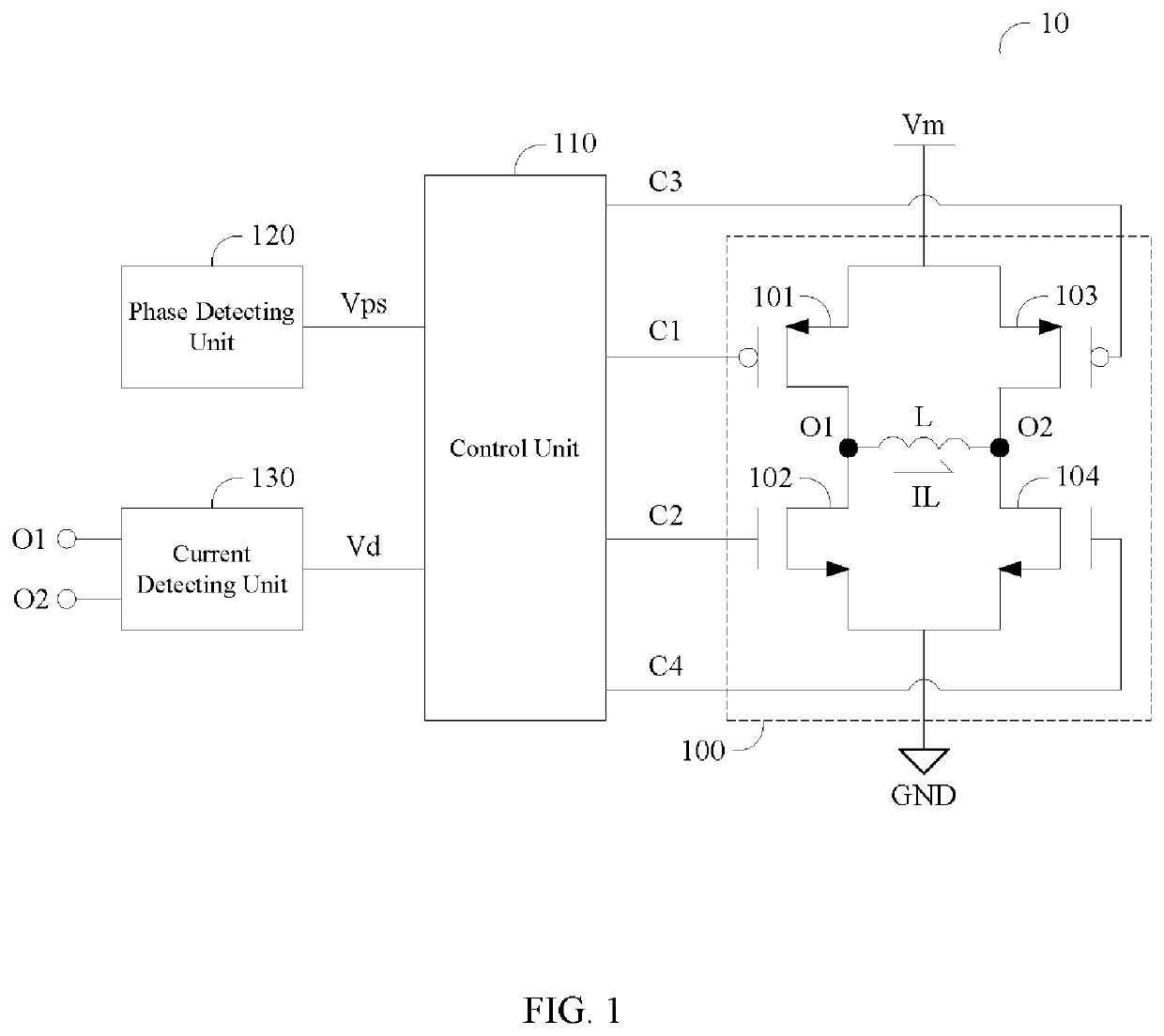
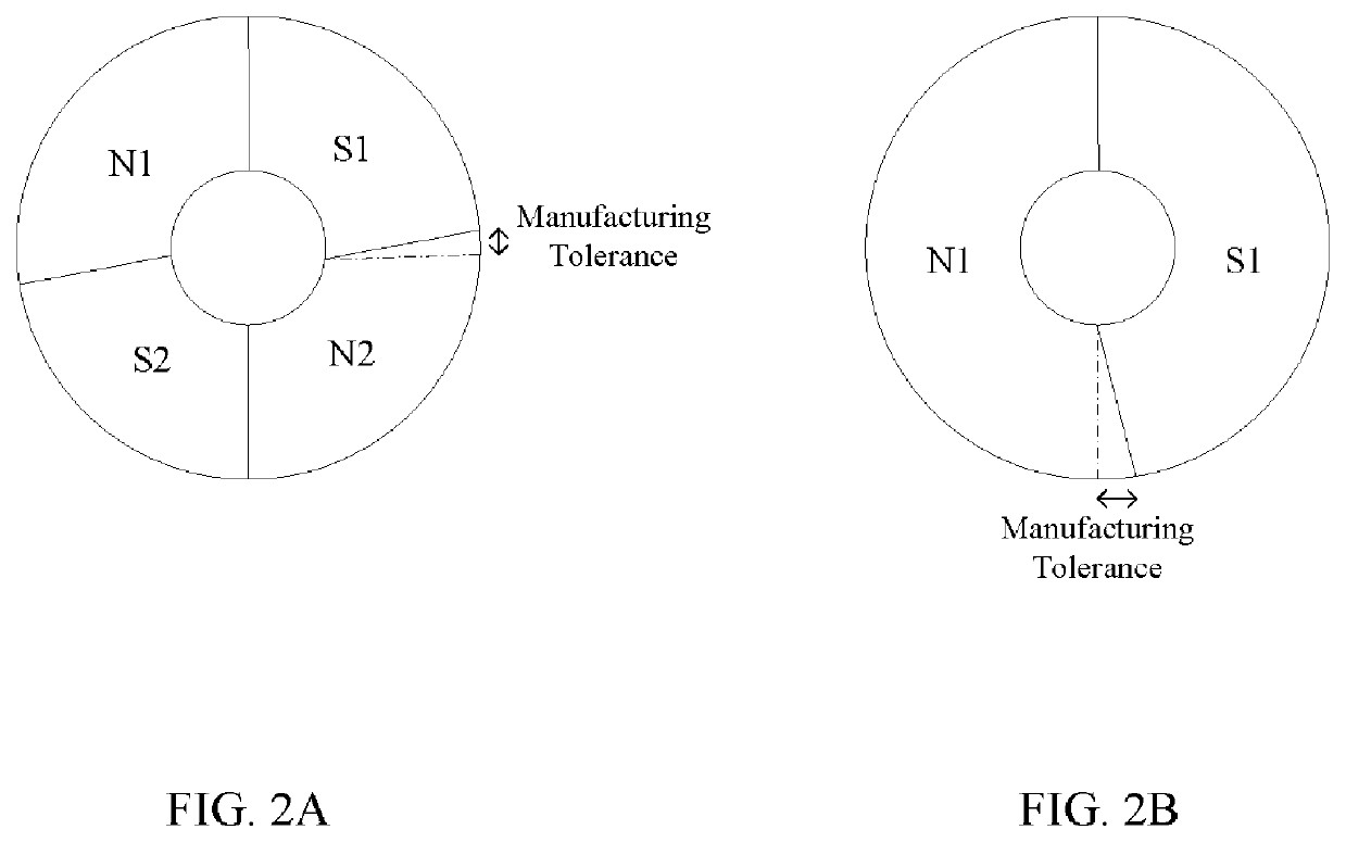
[0012]FIG. 1 is a circuit diagram showing a motor controller 10 according to one embodiment of the present invention. The motor controller 10 is used for driving a motor, where the motor has a motor coil L and a rotor. FIG. 2A is the schematic diagram of the rotor according to one embodiment of the present invention. The rotor is divided into four pole regions N1, S, N2, and S2 to switch phases, but the present invention is not limited to the number of the pole regions. In an ideal case, the size of each of the four pole regions should be equal to a quarter of the rotor. As shown in FIG. 2A, practically the size of each of the four pole regions is not equal to a quarter of the rotor due to a manufacturing error. Thus, when the rotor is divided into two pole regions, four pole regions, or more than four pole regions, in each case it is capable of defining a manufa...


PUM


Abstract

A motor controller is configured to reduce the motor noise. The motor controller is used for driving a motor, where the motor has a motor coil and a rotor. The rotor is divided into four pole regions N1, S1, N2, and S2 to switch phases. The four pole regions have a manufacturing tolerance and the pole region N1 has a time interval T1. The motor controller comprises a switch circuit, a control unit, a phase detecting unit, and a current detecting unit. The switch circuit is configured to supply a driving current to the motor coil. Based on the manufacturing tolerance and the time interval T1, the time point to detect the driving current is set to be a proportional time PT before the phase switching, where PT / T1 is greater than the manufacturing tolerance.

Description

BACKGROUND OF THE INVENTION1. Field of the Invention[0001]The present invention relates to a motor controller, and more particularly, to a motor controller which is capable of reducing the motor noise.2. Description of the Prior Art[0002]Generally, there still remains the current flowing through the motor coil due to the asymmetrical pole regions at the time point of phase switching, which results in a mechanical noise when the motor rotates. A prior-art method detects the current flowing through the motor coil at the time point of phase switching, so as to determine if the timing sequence of a plurality of driving signals needs to be adjusted or not in the next period, where the driving signals are configured to control a driving circuit. The driving circuit may be an H-bridge circuit. However, the rotor of the motor may be divided into a plurality of pole regions. When the sizes of the plurality of the pole regions differ due to a manufacturing tolerance, the prior-art method may ...

Claims


Application Information

Patent Timeline
Patent Type & Authority Applications(United States)
IPC IPC(8): H02P6/10H02P7/03H02P23/14H02P6/16G01R33/07G01R19/165
CPCH02P6/10H02P7/04G01R19/16538H02P6/16G01R33/07H02P23/14H02P6/26G01R33/072
Inventor CHU, CHIEN-LUN
Owner GLOBAL MIXED MODE TECH
Why Eureka
Try Eureka