
Optical fiber based bistatic radar

a bistatic radar and optical fiber technology, applied in the field of radar systems, can solve the problems of inability to obtain information, bistatic radar not receiving wide acceptance in comparison with monostatic, bistatic radar at least twice as expensive as monostatic radar, etc., and achieve the effect of simple, inexpensive and versatil

Inactive Publication Date: 2000-11-07
LI MING CHIANG
View PDF31 Cites 54 Cited by
  • Summary
  • Abstract
  • Description
  • Claims
  • Application Information

AI Technical Summary

Benefits of technology

Embodiments of the present invention advantageously satisfy the above-identified need in the art and provide a bistatic radar system which is simple, inexpensive, and versatile; which achieves synchronization between transmitting and receiving sites; and which does not require processing of a received signal at a receiving site. In particular, an embodiment of the inventive bistatic radar system comprises a transmitting radar site; a receiving radar site; and an optical fiber RF link system for transmitting RF signals from the receiving site to the transmitting site and for transmitting command and control signals from the transmitting site to the receiving site.

Problems solved by technology

Although monostatic radar systems are the most prevalent ones used, they suffer from a drawback in that unable to obtain information which will enable them to determine many important features of targets.
However, despite this, bistatic radar has not received wide acceptance in comparison with monostatic radar for the following reasons.
This is considered to be a drawback for a bistatic system since the cost of additional sites, i.e., the cost of additional personnel, hardware, and supporting facilities, makes a bistatic radar at least twice as expensive as a monostatic radar.
However, as the separation between the bistatic sites increases, surface attenuation will reduce the strength of the direct signal and degrade its quality.
Moreover, whenever there is a large separation between bistatic sites, the direct signal cannot be used to provide the reference information.
Although, in an alternative method, the reference information may be obtained by utilizing a stable clock or oscillator, this method suffers in that the use of clocks or oscillators severely restricts the versatility of a bistatic radar system.
Third, the volume of observation is limited to an intersection volume of the transmit antenna beam and the received antenna beam.
Thus, the use of high-gain antennas by the transmitting and receiving sites leads to inefficient use of the radar power since only the volume common to both beams is used during an observation, i.e., targets outside of the common volume are lost.
The use of multiple, simultaneous receiving beams increases the cost and complexity of the bistatic radar system, since the use of multiple, simultaneous receiving beams requires dedicated antennas, receivers, and processors for each receiving beam.
Since, mechanical beam chasing is impossible, one must use a phase array to chase the transmitted pulse and, this further complicates the problem of resolving volumetric limitation.
However, the use of such a command and control link suffers from several drawbacks.
A first drawback is that the digital link entails overhead time which occurs as the result of radio frequency (RF) to digital conversion at the receiving site and in digital signal processing of the received radar signal.
A second drawback occurs as a result of the need to correct any detected lack of coordination promptly.
The correction incurs further overhead in time because such correction requires conversion from analog to digital at the transmitting site as well.

Method used


Image

  • Optical fiber based bistatic radar
  • Optical fiber based bistatic radar
  • Optical fiber based bistatic radar

Examples


embodiment 100

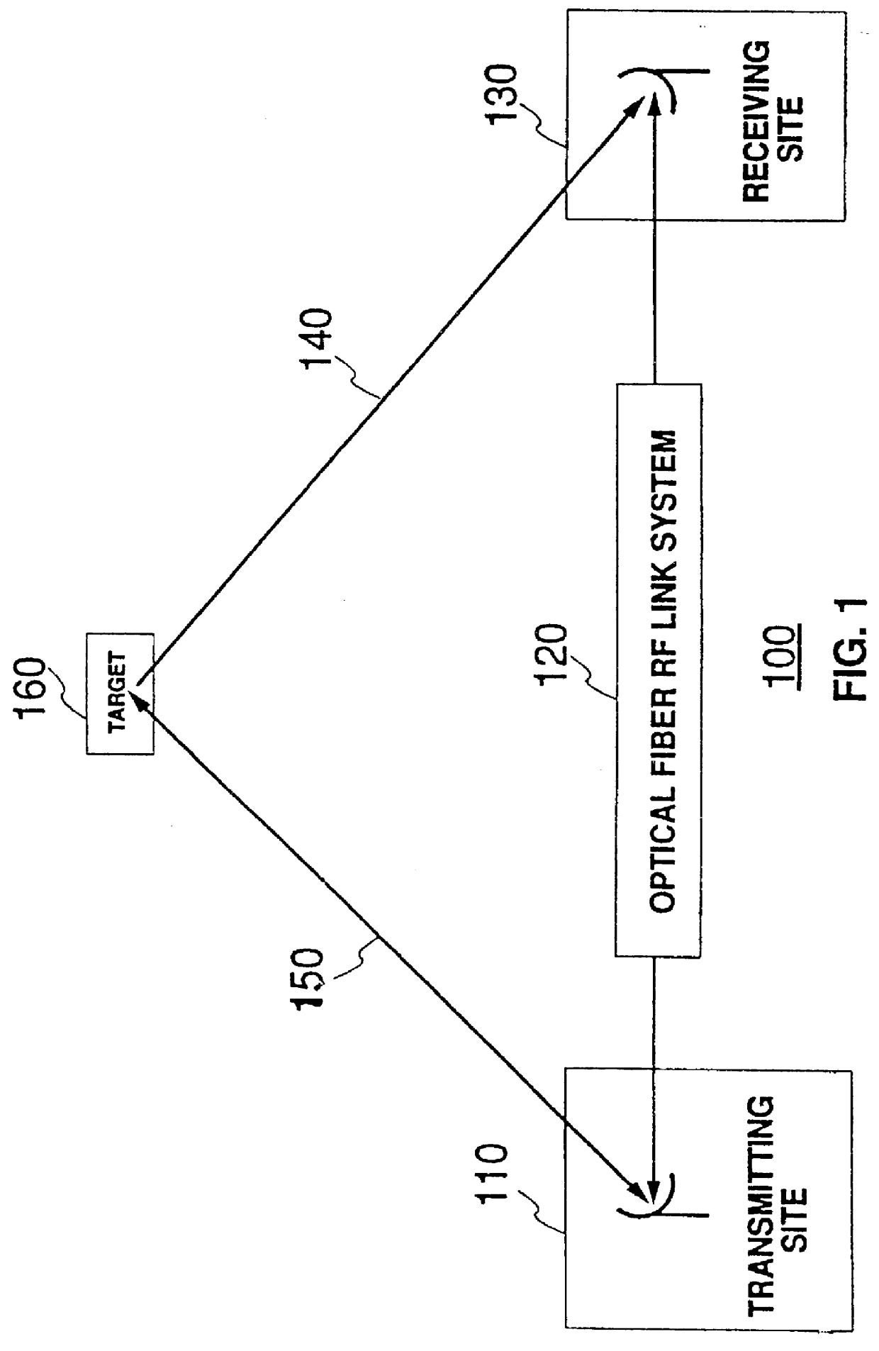
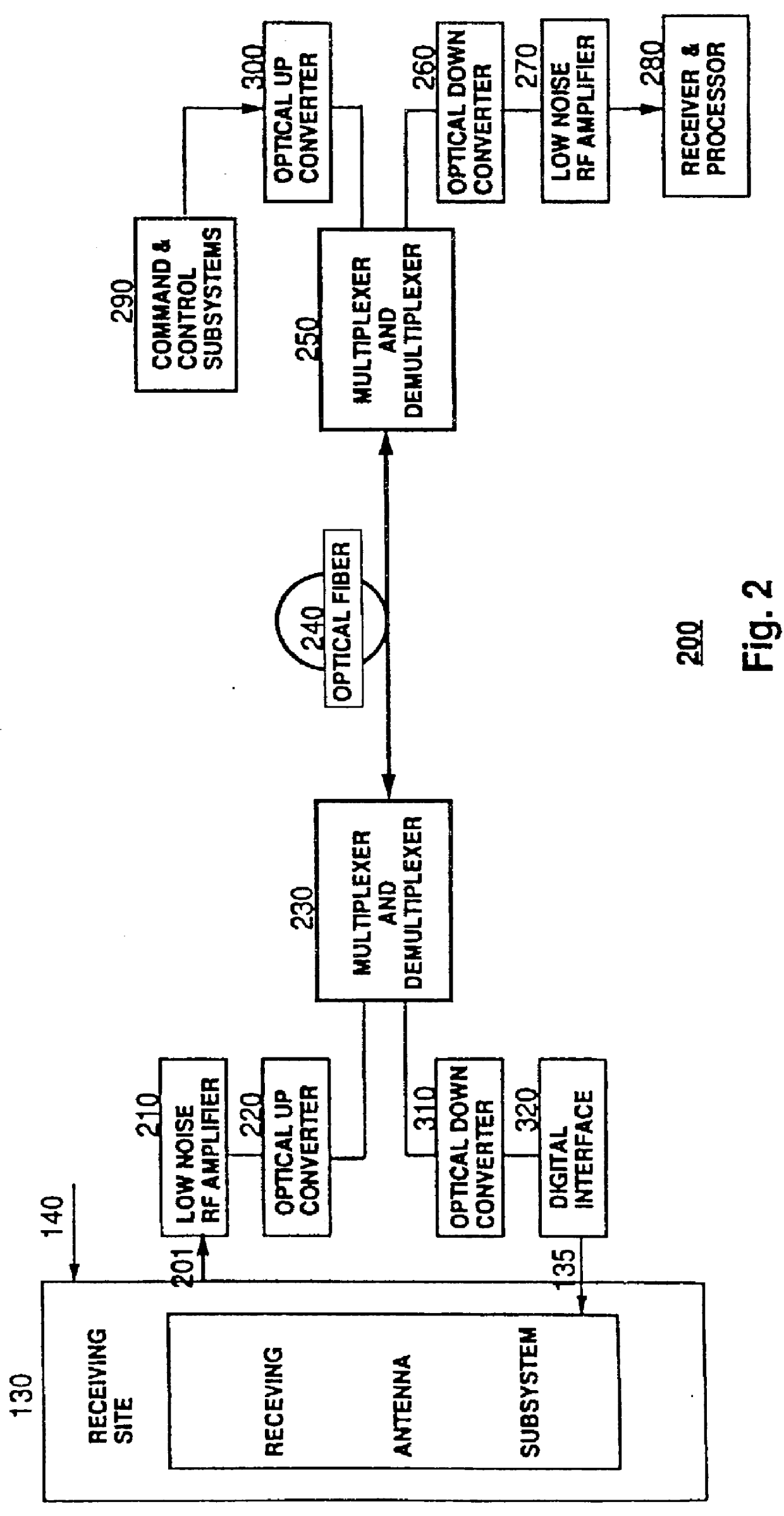
FIG. 1 shows a block diagram of embodiment 100 of a bistatic radar system ("BRS") which is fabricated in accordance with the present invention. As shown in FIG. 1, BRS 100 is comprised of transmitting site 110 ("TS 110"), receiving site 130 ("RS 130"), and optical fiber RF link system 120 ("OFRLS 120"). Although FIG. 1 shows RS 130 as being a single receiving site, embodiments of the present invention include systems wherein RS 130 is comprised of a multiplicity of receiving sites.

TS 110 in FIG. 1 is much like a transmitting site which is found in an ordinary monostatic radar site. It can receive and process its own monostatic radar signals and, in accordance with the present invention, it is also equipped with receivers and processors to receive and process bistatic radar signals as well. Thus, monostatic and bistatic modes of operations are executed at TS 110. In particular, TS 110 is comprised of antenna subsystems, transmitters, receivers, processors, command and control subsyst...

embodiment 600

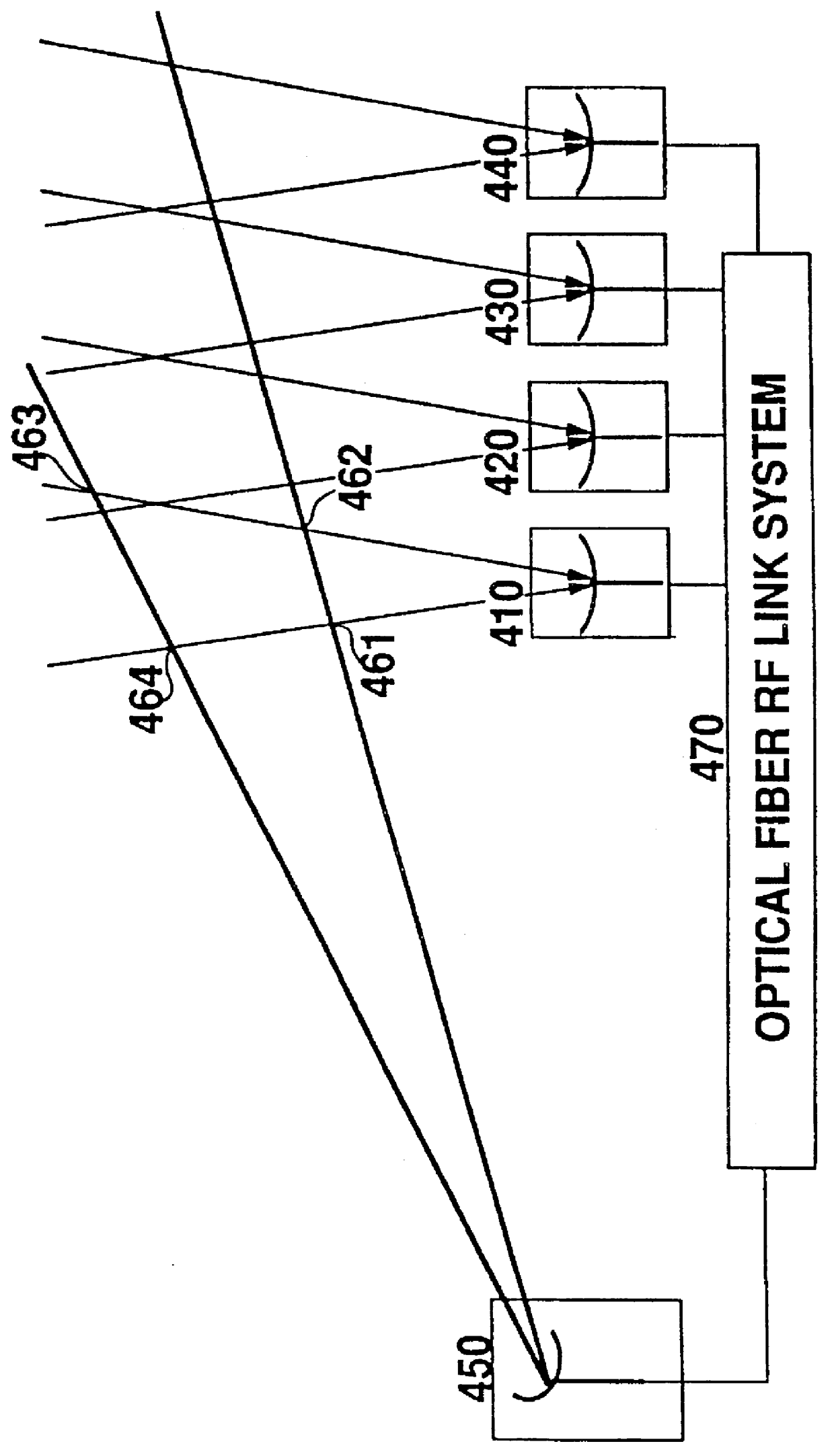
FIG. 5 shows a block diagram of embodiment 600 of bistatic RF network which is fabricated in accordance with the present invention. Optical fiber based bistatic radars, optical and infrared sensors, video and infrared cameras are merged together to form a complex network. The detailed architecture of a bistatic RF network varies with the needs. The main function of a bistatic RF network is on bistatic radar detections and measurements for achieving various objectives of operation and management. Antennas, sensors and cameras need not be at fixed locations, and may be on the optical fiber tethered vehicles.

As shown in FIG. 5, receivers 610, processors 620, command and control subsystems 630, are housed in a management center 640 for an effective utilization of resources and purpose of reducing operation costs. For a purpose of illustration, the bistatic RF network 600 is being used for airport operation and management. In accordance with the present invention OFRLS 650 sends command ...


PUM


Abstract

A bistatic radar system includes a transmitting radar site; a receiving radar site; and an optical fiber RF link system for transmitting RF signals from the receiving site to the transmitting site and for transmitting command and control signals from the transmitting site to the receiving site.

Description

TECHNICAL FIELD OF INVENTIONThe present invention relates to a radar system and, in particular, to a bistatic radar system which utilizes optical fibers to transmit received radar signals from a receiving site to a transmit site.BACKGROUND OF THE INVENTIONMost radar systems in use today are monostatic radar systems, i.e., they are comprised of a single site to perform both a transmitting and a receiving function. Although monostatic radar systems are the most prevalent ones used, they suffer from a drawback in that unable to obtain information which will enable them to determine many important features of targets.It is well known in the art that a bistatic radar system can overcome the above-defined drawback. However, despite this, bistatic radar has not received wide acceptance in comparison with monostatic radar for the following reasons. First, at least two sites are required for a bistatic system. This is considered to be a drawback for a bistatic system since the cost of additi...

Claims


Application Information

Patent Timeline
IPC IPC(8): G01S13/00G01S7/00
CPCG01S13/003G01S7/003
Inventor LI, MING-CHIANG
Owner LI MING CHIANG
Learn More