Refrigeration compressor

Inactive Publication Date: 2001-01-16
EMERSON CLIMATE TECH INC
View PDF77 Cites 4 Cited by
  • Summary
  • Abstract
  • Description
  • Claims
  • Application Information

AI Technical Summary

Benefits of technology

The present invention relates generally to refrigeration compressors and more specifically to such compress

Problems solved by technology

However, the higher viscosity of the oil as compared to refrigerant gas creates an increased drag on rotation of the rotor resulting in increased power consumption.
This problem is further aggravated in scroll

Method used


Image

  • Refrigeration compressor
  • Refrigeration compressor
  • Refrigeration compressor

Examples


Embodiment Construction

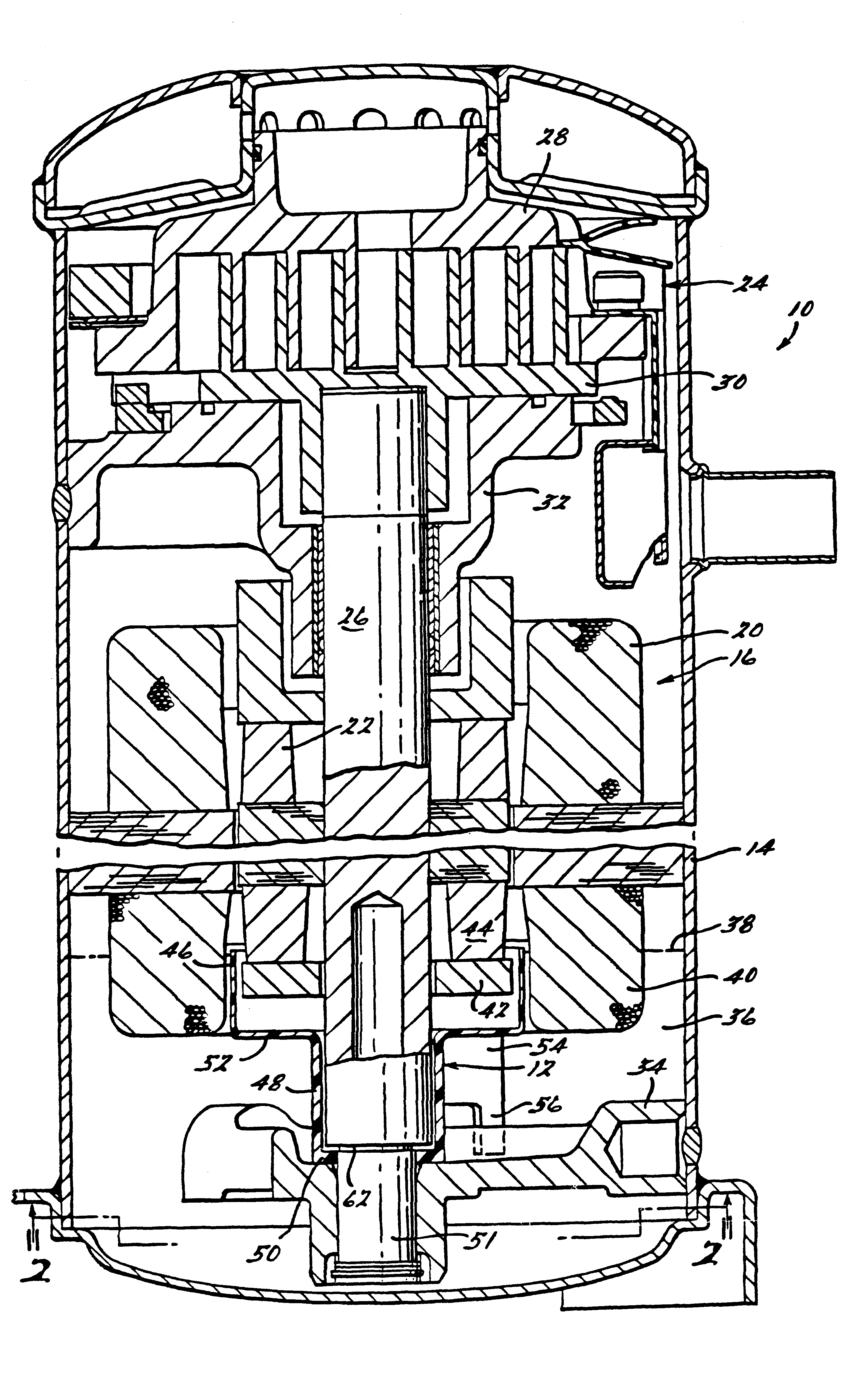
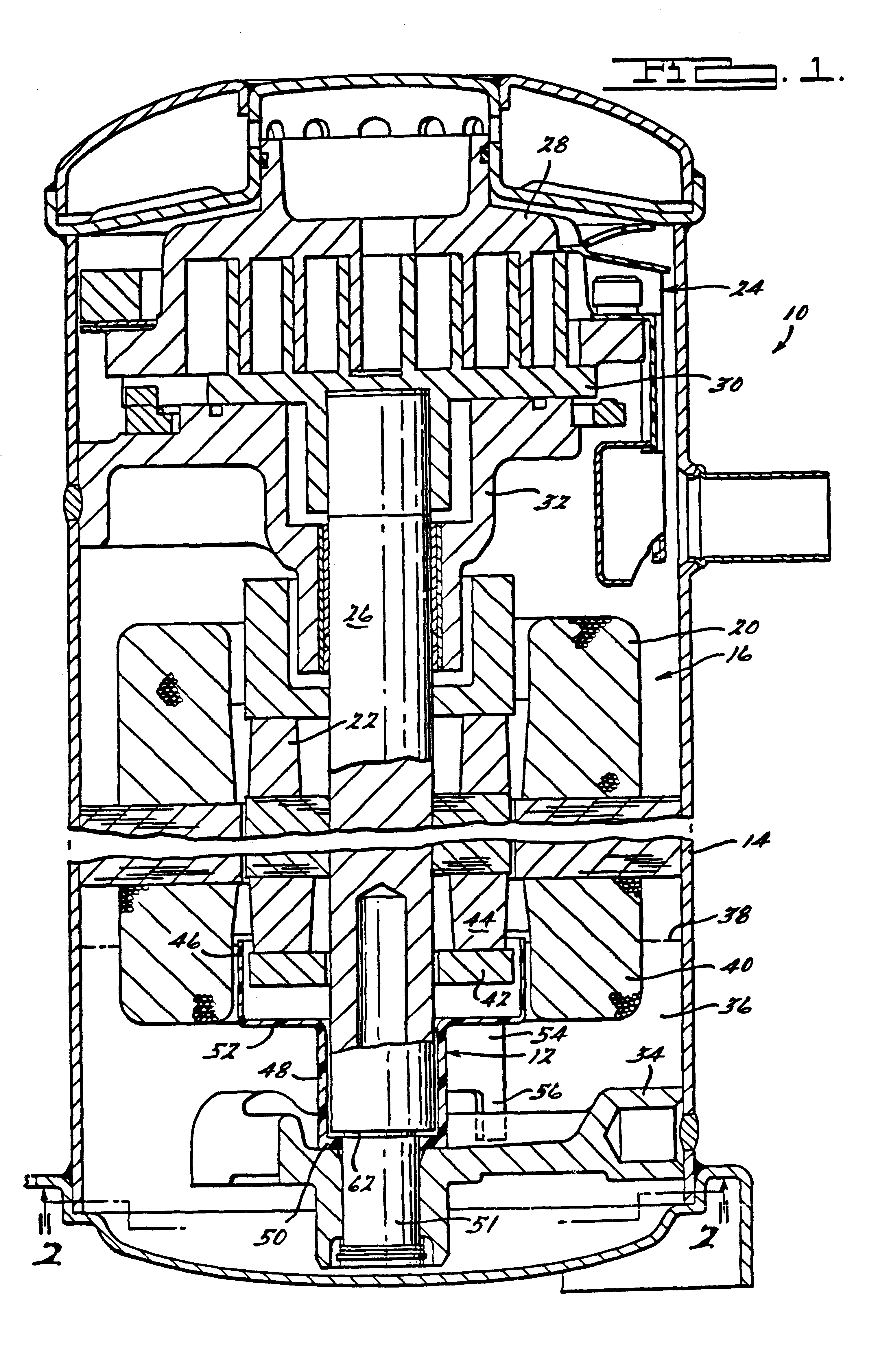
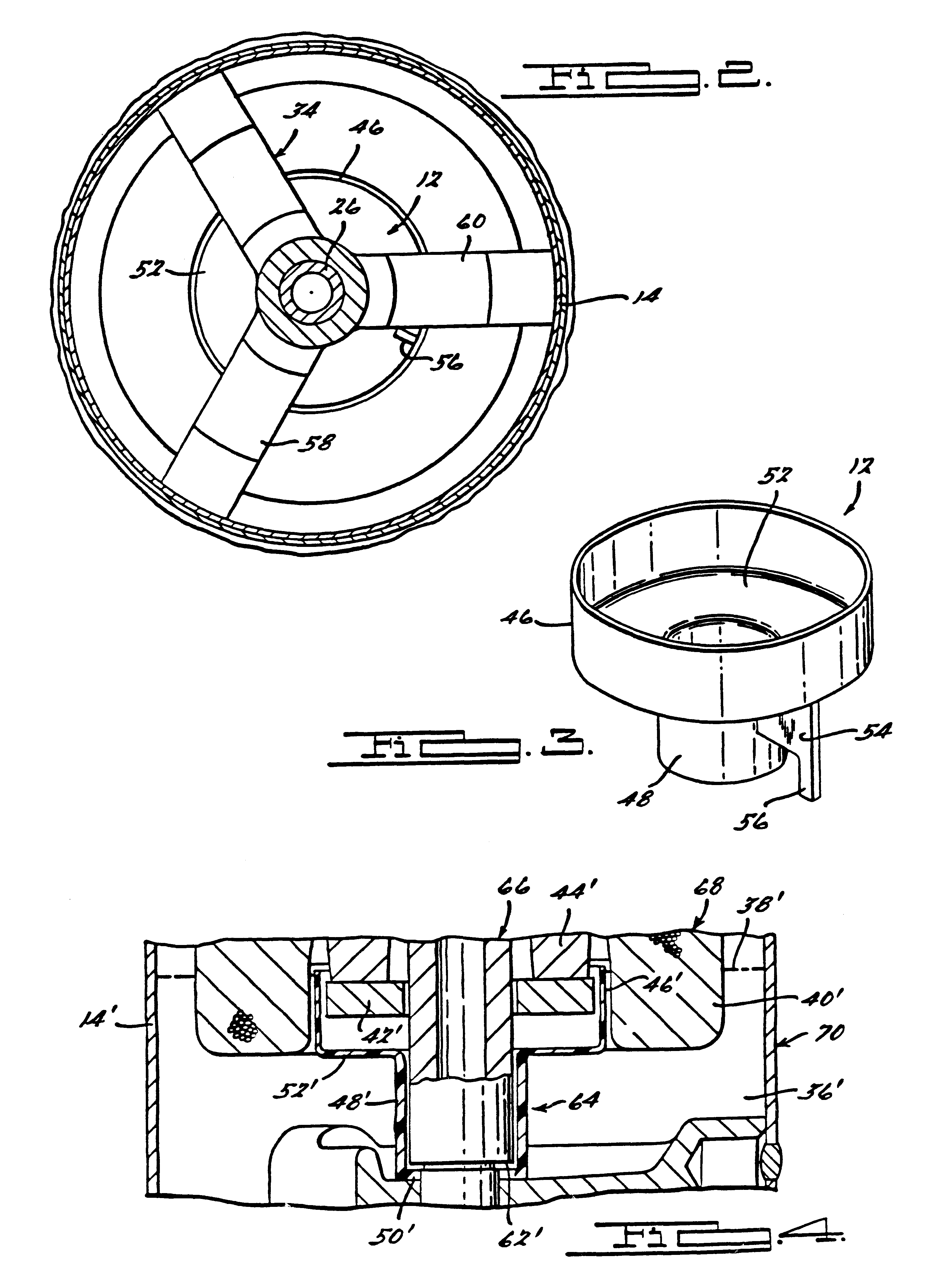
Referring now to the drawings and more specifically to FIG. 1, there is shown a hermetic refrigeration compressor 10 incorporating a shield 12 all in accordance with the present invention.

Compressor 10 comprises an outer shell or housing 14 within the lower portion of which is disposed an electric motor 16 including a stator 20 and a rotor 22. Motor 16 is operative to drive a compressor assembly 24 disposed in the upper portion of shell 14 via a drive shaft 26 extending therebetween and to which rotor 22 is secured adjacent the lower end. As shown, compressor assembly 24 is of the scroll type and incorporates an upper fixed scroll member 28 and a lower scroll member 30 which is driven by drive shaft 26 in orbiting motion relative to the fixed scroll member 28. Drive shaft 26 is rotatably supported within shell 14 by means of upper and lower bearing assemblies 32 and 34 respectively each of which are fixedly secured to shell 14. Compressor 10 is described in greater detail in present...


PUM


Abstract

A refrigeration motor compressor assembly has a housing including a lubricant sump in the bottom thereof into which the lower end of the drive shaft and associated rotor extend. A shield is provided which is positioned by the drive shaft and extends above the oil level in the sump in surrounding spaced relationship to the lower end of the rotor. As the rotor rotates within the shield, lubricant contained therein is thrown out of the surrounding shield and a close fit between the shield and the shaft restricts return flow of lubricant into the area occupied by the rotating rotor.

Description

BACKGROUND AND SUMMARY OF THE INVENTIONThe present invention relates generally to refrigeration compressors and more specifically to such compressors incorporating shields for reducing the lubricating oil level in the area surrounding the rotating rotor.Typical refrigeration compressors incorporate a lubricant sump in the lower or bottom portion of the housing into which the drive shaft extends so as to pump lubricant therefrom to the various portions requiring lubrication. In addition, the lubricant also often acts to aid in removal of heat from the various components. In order to insure sufficient lubricating oil is contained within the sump to assure adequate lubrication and / or cooling of the moving parts while also minimizing the overall height of the housing, it is sometimes necessary that the oil level extend above the rotating lower end of the rotor. However, the higher viscosity of the oil as compared to refrigerant gas creates an increased drag on rotation of the rotor resu...

Claims


Application Information

Patent Timeline
IPC IPC(8): F04C29/02F25B31/02F25B31/00
CPCF04C29/028F25B31/026
Inventor ELSON, JOHN P.
Owner EMERSON CLIMATE TECH INC
Why Eureka
Try Eureka