Spinal fixation device

a technology of fixation device and spine, which is applied in the field of spinal fixation device, can solve the problems of screw that may slowly become less secure, and achieve the effects of reducing the risk of fracture, facilitating healing, and facilitating healing

Inactive Publication Date: 2001-12-18
SPINEOLOGY
View PDF34 Cites 140 Cited by
  • Summary
  • Abstract
  • Description
  • Claims
  • Application Information

AI Technical Summary

Benefits of technology

The invention provides a method and device for fixing two or more vertebrae. The process is elegantly simple and solves many of the problems attendant with previous devices.
Each vertebra to be joined is prepared by forming a partial annular cut, as by a hole saw, preferably leaving the core plug of bone in place. A hollow screw is threaded into the annular ring recess thus formed. A channel is cut in the vertebral bone between each of the screws to accommodate a rod that is placed over each screw. A locking cap over each screw secures the rod to the screws and thereby fixes the spine as desired.
The method and device provide many advantages. The hollow screws are exceptionally strong, having greater holding surface area than conventional solid screws. The rod is held in the screw between two widely spaced slots. The rod is also held firmly by a third point by a dimple on the locking cap. The rod is secured to the screws by at least three points of fixation over a much greater distance than traditional systems. This provides a linkage which is significantly greater in terms of mechanical stability over the prior art.
By varying the cross-section geometric structure and diameter of the rod, various degrees of stiffness may be imparted. Also, by varying the geometric cross-section structure of the rod, stiffness may be imparted selectively in the appropriate plane of motion. For instance, if increased flexion-extension stability is desired, the rod can be oriented in the flexion-extension plane and elongated such that it will provide greater stiffness in flexion-extension than in lateral bending. Such a feature will allow the surgeon to define the plane of stiffness necessary to match the pathology encountered.
The process is very simple, requiring only the drilling of a single hole saw cut in each vertebra, formation of channels therebetween and installation of the hollow screws, placement of the rod and securement with the locking caps.

Problems solved by technology

Prior art devices use screws that may slowly become less secure with age and the inevitable micromotion that occurs between the screw and the vertebral bone.

Method used


Image

  • Spinal fixation device
  • Spinal fixation device
  • Spinal fixation device

Examples


Embodiment Construction

is hereafter described with specific reference being made to the drawings in which:

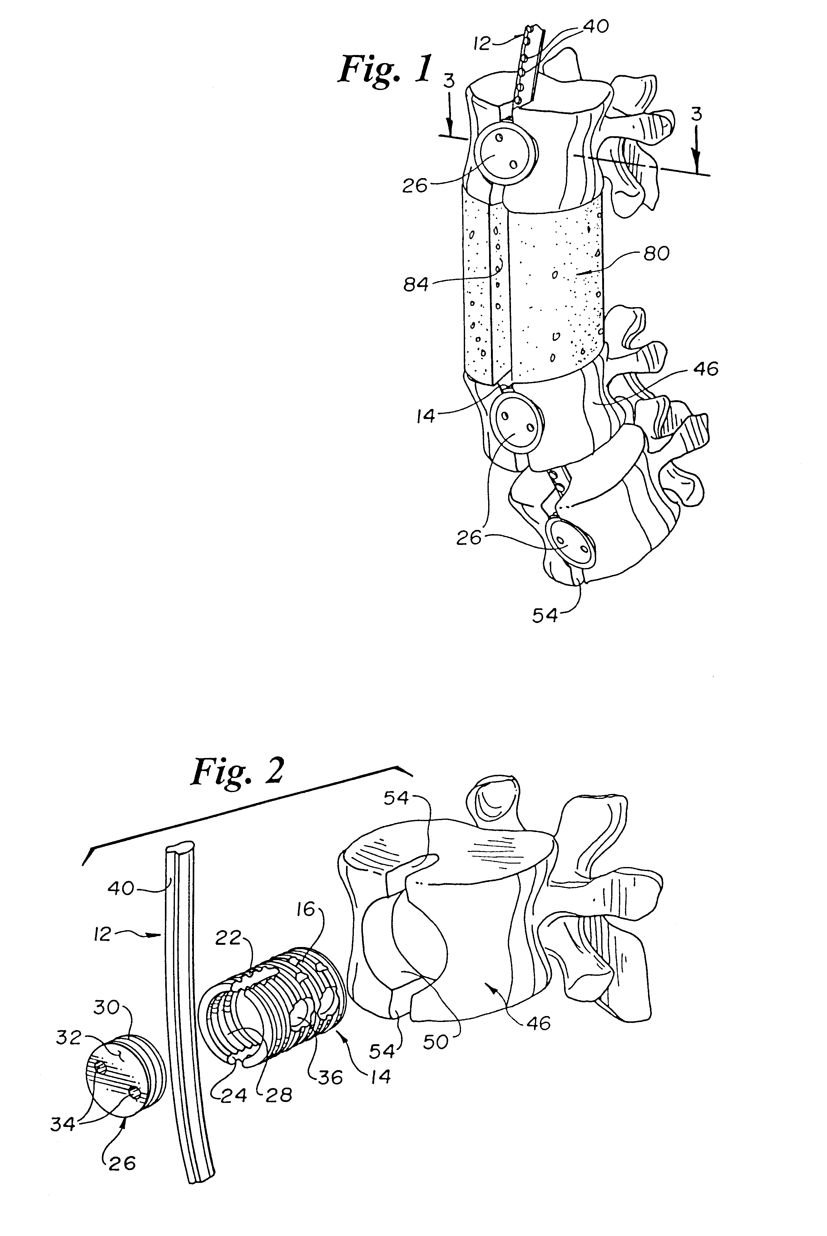
FIG. 1 is a perspective view of the device of the invention securing vertebrae together;

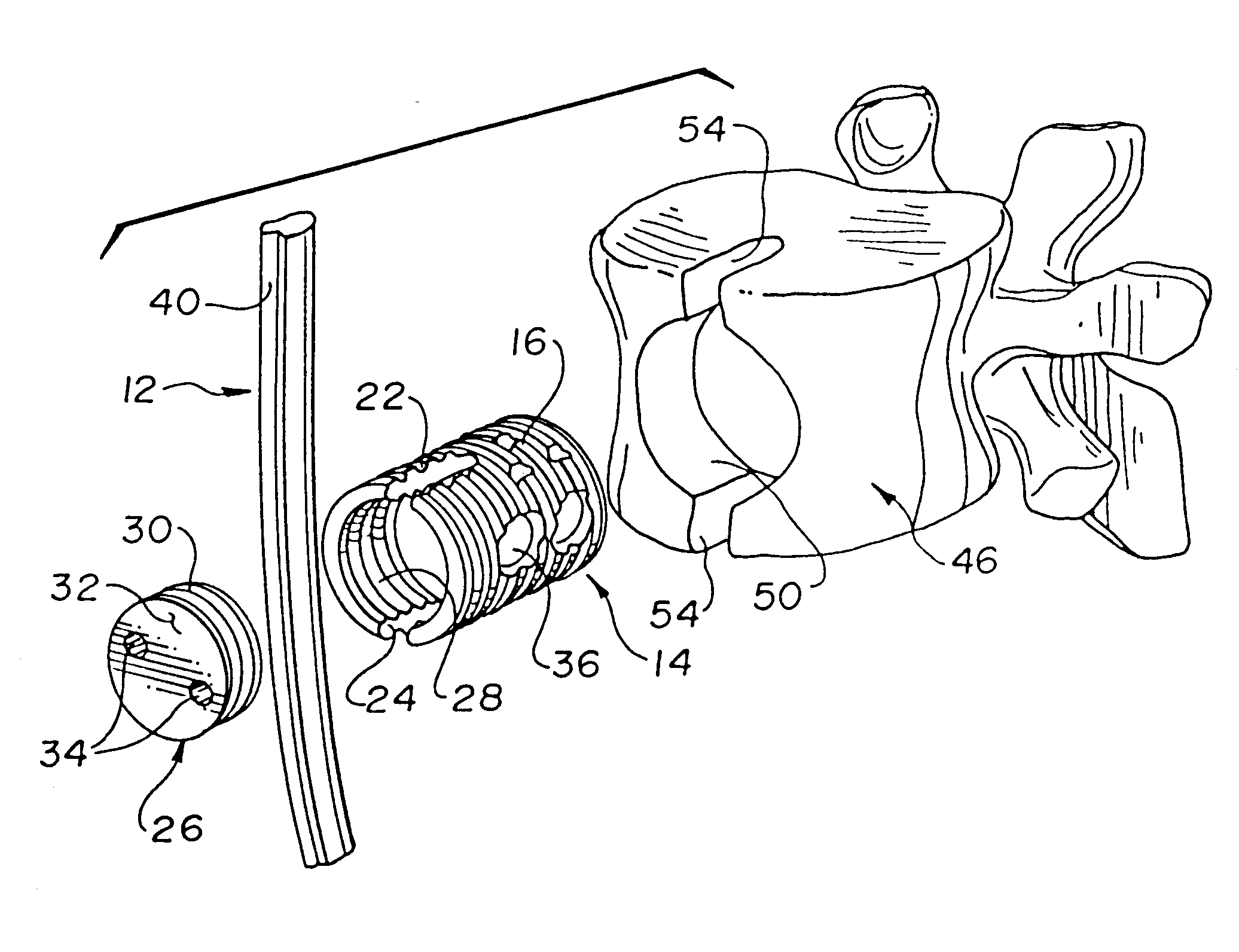
FIG. 2 is an exploded view of the rod, screw, cap and prepared vertebrae;

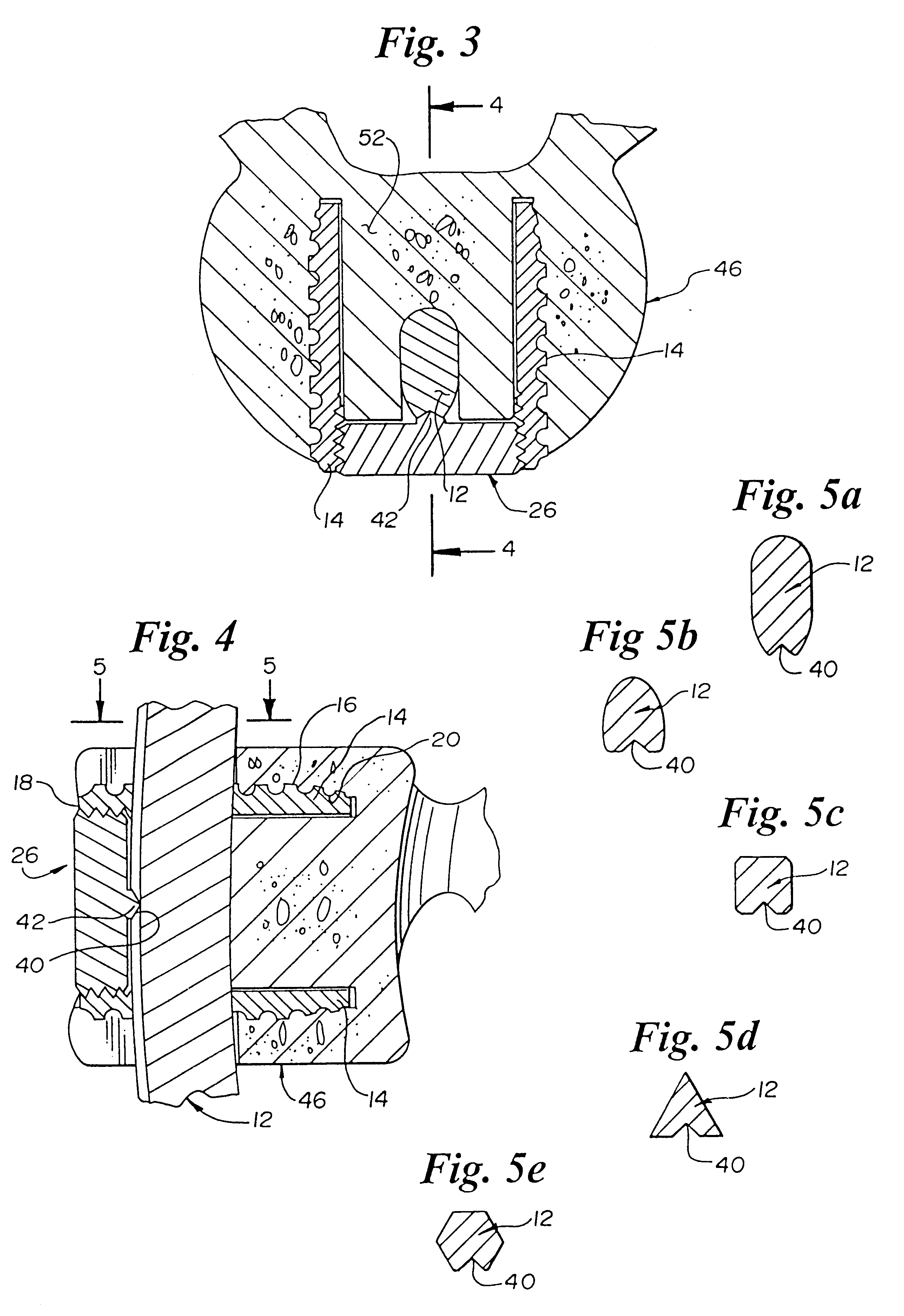
FIG. 3 is a cross-sectional view taken through line 3--3 of FIG. 1;

FIG. 4 is a cross-sectional view taken through line 4--4 of FIG. 3;

FIG. 5a is a cross-sectional view taken through line 5--5 of FIG. 4 showing the rod in cross-section;

FIG. 5b is a cross-sectional view taken through line 5--5 of FIG. 4 showing an alternate rod in cross-section;

FIG. 5c is a cross-sectional view taken through line 5--5 of FIG. 4 showing an alternate rod in cross-section;

FIG. 5d is a cross-sectional view taken through line 5--5 of FIG. 4 showing an alternate rod in cross-section;

FIG. 5e is a cross-sectional view taken through line 5--5 of FIG. 4 showing an alternate rod in cross-section;

FIG. 6 is a cross-sectional view similar to FIG. 3 with an overcap design;

FIG....


PUM


Abstract

An spinal fixation device for stabilizing vertebrae. A hollow screw is inserted into a hole saw recess in each adjoining vertebrae. A channel is cut into the vertebrae into which a joining rod is inserted such that no part of the device protrudes above the bone. A locking cap is used to secure the rod to the screws.

Description

BACKGROUND OF THE INVENTION1. Field of the InventionThis invention relates to a device for fixing adjacent vertebrae to each other using a rod and unique hollow screws.2. Description of the Related ArtFixation (or fusion) of vertebral columns with bone material or rods and plates is a common, long practiced surgical method for treating a variety of conditions. Many of the existing procedures involve components that protrude outwardly that may contact and damage a body part, such as the aorta, the vena cava, the sympathetic nerves, the intestine and the ureter. Also, many constructions involve components that may loosen and cause undesirable problems. A Dunn device was on the market until pulled by the U.S. Food & Drug Administration because of problems with delayed rupture of the aorta secondary to the device being so bulky as to contact the aorta, erode its surface and lead to fatal hemorrhage in several cases.U.S. Pat. No. 5,152,303 issued to Allen on Oct. 6, 1992 relates to an an...

Claims


Application Information

Patent Timeline
Patent Type & Authority Patents(United States)
IPC IPC(8): A61B17/70A61B17/88A61F2/30A61F2/46A61F2/44A61F2/00A61F2/28A61B17/58
CPCA61B17/70A61B17/701A61B17/7032A61B17/7076A61F2/30744A61F2/44A61F2/442A61F2/4425A61F2/446A61F2/4465A61F2/4611A61F2002/2835A61F2002/30125A61F2002/30131A61F2002/30143A61F2002/30154A61F2002/30156A61F2002/30158A61F2002/30187A61F2002/30225A61F2002/3023A61F2002/30235A61F2002/30329A61F2002/30405A61F2002/30507A61F2002/30594A61F2002/30616A61F2002/30785A61F2002/3082A61F2002/3085A61F2002/449A61F2220/0025A61F2220/0033A61F2230/0008A61F2230/0013A61F2230/0017A61F2230/0021A61F2230/0023A61F2230/0026A61F2230/0034A61F2230/0069A61F2310/00023A61F2310/00179A61F2002/30331A61F2/4637A61F2002/30593A61F2/4603A61F5/00
Inventor KUSLICH, STEPHEN D.
Owner SPINEOLOGY
Why Eureka
Try Eureka