
Angle measuring system with a clampable shaft

a technology of clamping shaft and measuring system, which is applied in the direction of couplings, instruments, mechanical equipment, etc., can solve the problems of axial displacement, radial spreading of the slitted shaft end, and other elements, and achieve the effect of simple clamping, simple construction and reliable clamping

Inactive Publication Date: 2005-11-22
HEIDENHAIN CORP
View PDF13 Cites 1 Cited by
  • Summary
  • Abstract
  • Description
  • Claims
  • Application Information

AI Technical Summary

Benefits of technology

[0007]It is an object of the invention to disclose an angle measuring system which is simply constructed and which makes possible a dependable and simple clamping of the shaft with a driveshaft.

Problems solved by technology

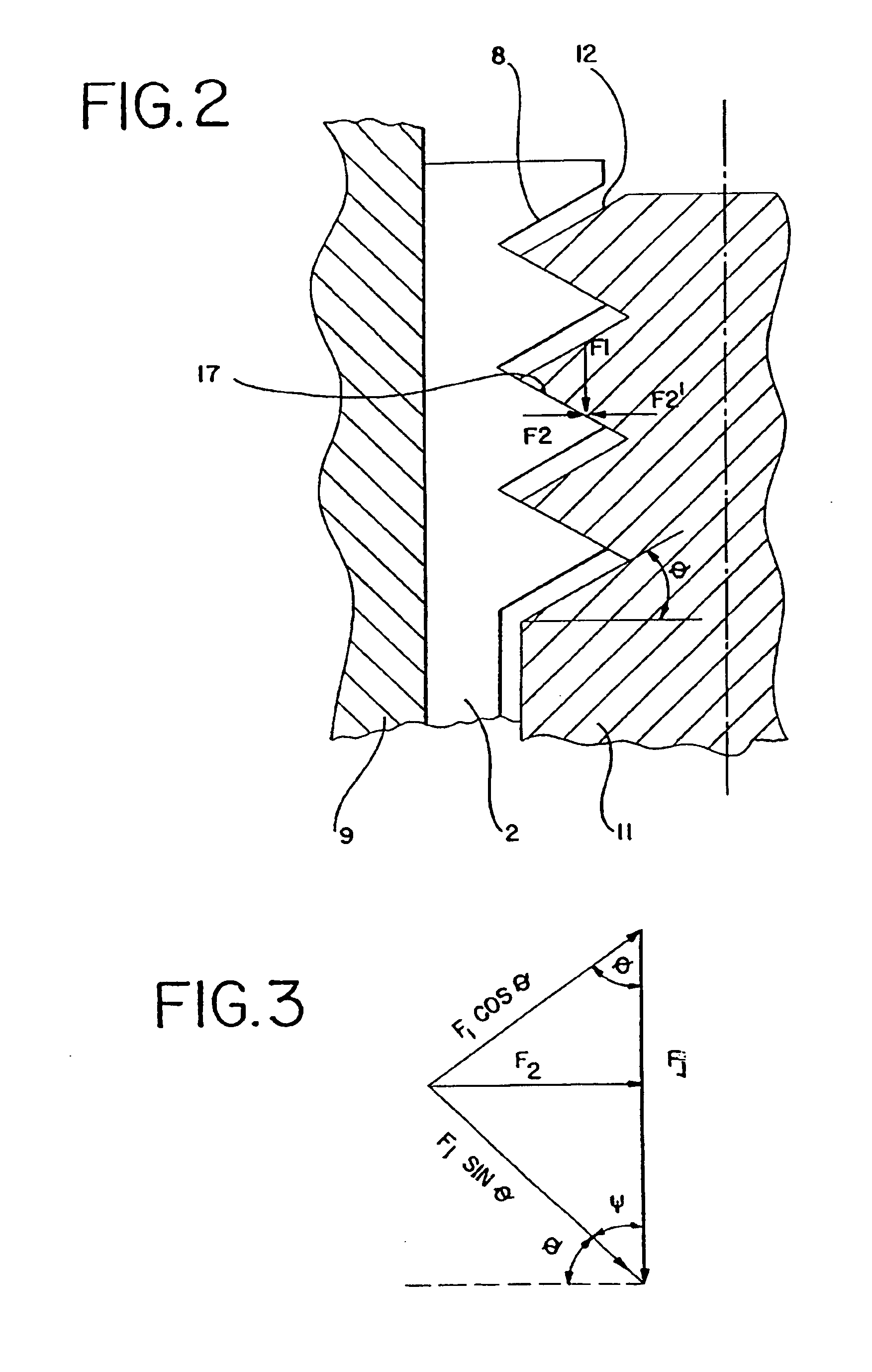
The thread flanks of the screw are displaced in the axial direction by turning the screw, which causes an axial displacement of the wedge and thus radial spreading of the slitted shaft end.
All known measuring systems have the disadvantage that, in addition to the screw, other elements, are still required for spreading.

Method used


Image

  • Angle measuring system with a clampable shaft
  • Angle measuring system with a clampable shaft
  • Angle measuring system with a clampable shaft

Examples


Embodiment Construction

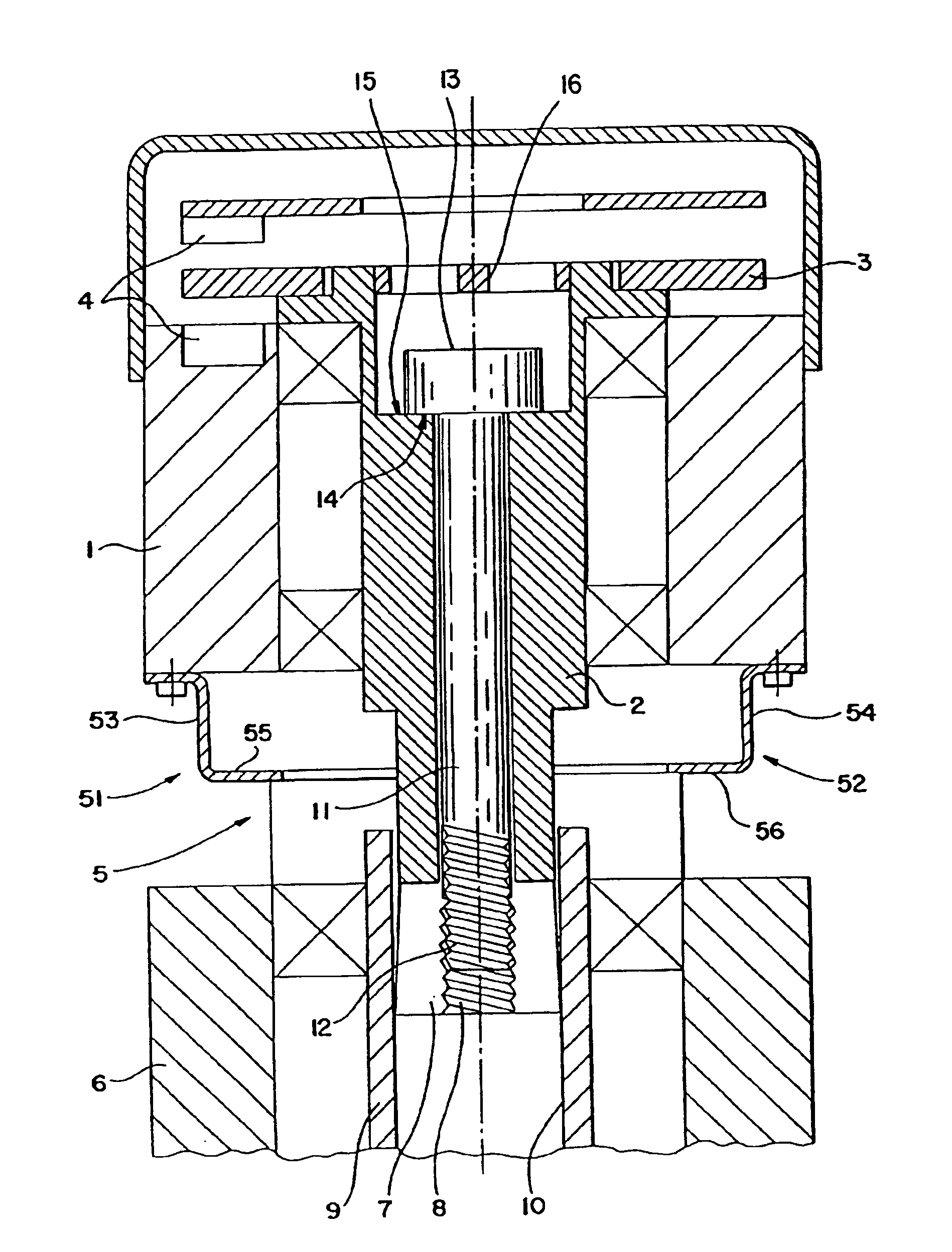
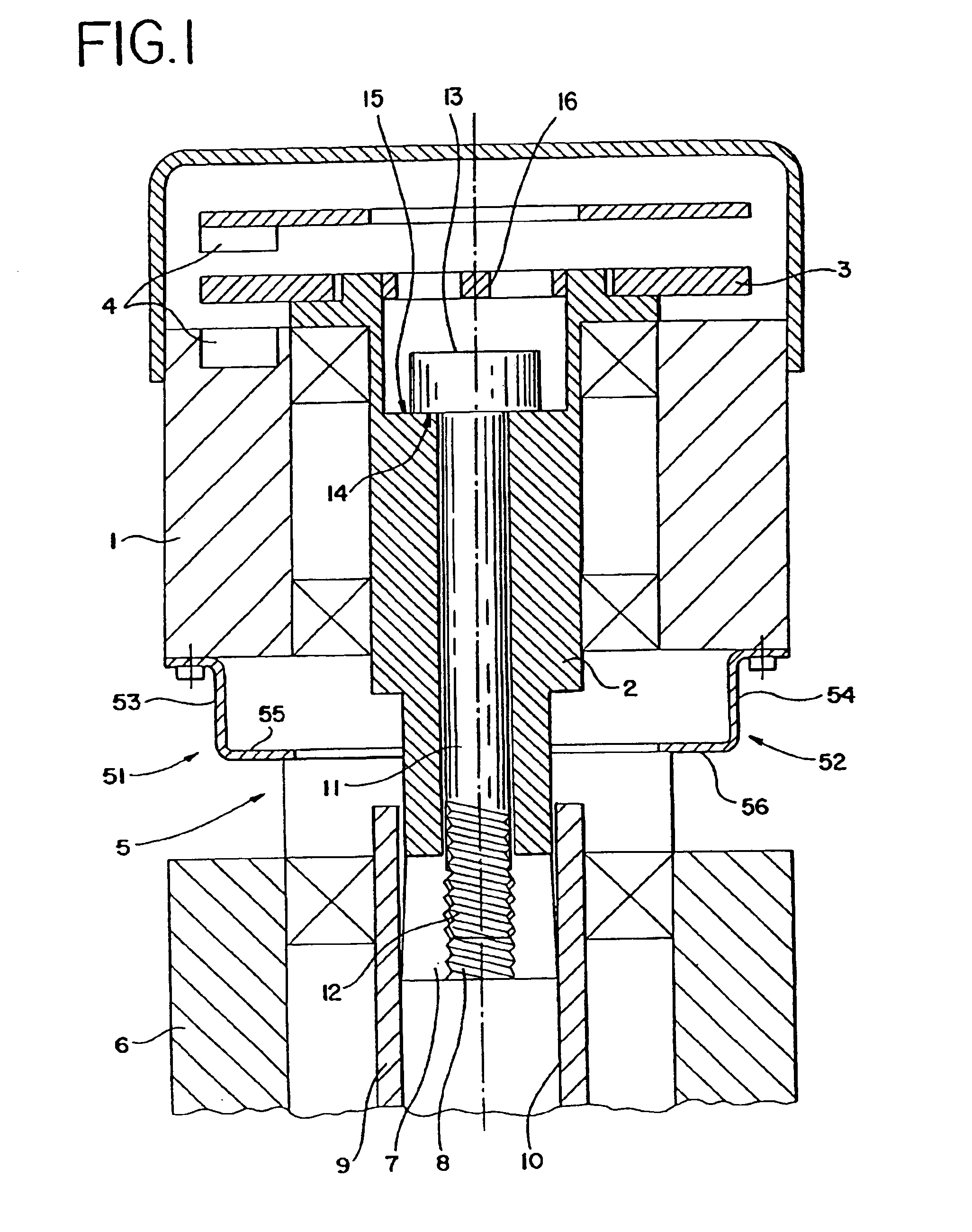
[0012]The angle measuring system shown in FIG. 1 includes a stator 1, a pick-up shaft 2, a coding disk 3, a scanning unit 4, a coupling 5, and a stationary element 6 of a drive unit, for example, a motor. The pick-up shaft 2 is preferably continuously hollow and is rotatably seated in the stator 1. The coding disk 3 is fastened to a first end of the pick-up shaft 2 by glue, for example. In a preferred embodiment an incremental or absolute coding is placed on the coding disk 3. The coding disk 3 is scanned by the scanning unit 4 which emits position-dependent electrical signals as is well known to those of ordinary skill in the art and thus need not be described in detail herein.

[0013]The stator 1 is fastened by coupling 5 to the stationary element 6. The coupling 5 assures a connection, fixed against relative rotation, of the stator 1 and the stationary element 6, but permits compensating movements between these two elements in all directions. The coupling 5 is especially rigid and ...


PUM


Abstract

The angular measuring system has a hollow pick-up shaft whose end is slitted, and the slitted area has an interior thread. A screw with an exterior thread is provided for clamping the pick-up shaft in a bore of a driveshaft. The screw is turned into the pick-up shaft until it is axially supported on a detent. By further turning of the screw the thread flanks of the interior thread and of the exterior thread cause the slit end of the pick-up shaft to be spread open radially.

Description

FIELD OF THE INVENTION[0001]The present invention relates to an angle measuring system with a coding disk for measuring the angular position of a pick-up shaft having a clamping device for clamping the pick-up shaft, fixed against relative rotation, to a driveshaft of a drive unit. The pick-up shaft has axial slits in the clamping area and can be radially spread open by an actuating element.BACKGROUND OF THE INVENTION[0002]U.S. Pat. No. 4,652,748 discloses an angle step indicator. It consists of a housing in which a hollow shaft is rotatably seated. A coding disk for measuring the angular position of the shaft with respect to a scanning unit fastened to the housing is fastened on this shaft, fixed against relative rotation. One end of the shaft is slitted and has a conical interior bore on which the conical tip of a pin acts. The pin is axially displaceable by a screw inserted into the other end of the shaft so that the slitted end of the shaft is spread open. The shaft of the angle...

Claims


Application Information

Patent Timeline
Patent Type & Authority Patents(United States)
IPC IPC(8): G01D5/26G01D5/347
CPCG01D5/34738F16D1/05F16D2001/0903F16D1/097
Inventor SETBACKEN, ROBERTGOEDEN, RICHARD MICHAEL
Owner HEIDENHAIN CORP
Learn More