
Self-propelled brushless surface cleaner with reclamation

a self-propelled, surface cleaner technology, applied in the direction of cleaning equipment, cleaning equipment, chemistry apparatus and processes, etc., can solve the problem that no prior art surface cleaner can achieve, and achieve the effect of improving cleaning capabilities

Inactive Publication Date: 2006-12-12
CLEAN UP AMERICA
View PDF18 Cites 13 Cited by
  • Summary
  • Abstract
  • Description
  • Claims
  • Application Information

AI Technical Summary

Benefits of technology

[0008]Accordingly, it is an object of the present invention to provide a surface cleaner having improved cleaning capabilities for cleaning hard flat industrial surfaces such as ship decks, airport runways, streets, parking surfaces and industrial floors.
[0010]Yet another object of the present invention is to provide a surface cleaner that can be operated by a single person.
[0011]Still another object of the present invention is to provide a surface cleaner that effectively scrubs a surface without the use of brushes or other types of surface-contacting scrubbing devices.
[0012]A still further object of the present invention is to provide a self-propelled surface cleaner that is easy to maneuver on a surface to be cleaned.
[0013]Yet another object of the present invention is to provide a surface cleaner that reclaims its cleaning fluid while trapping loosened surface contaminants in order to prevent any toxic runoff.

Problems solved by technology

Unfortunately, none of the prior art surface cleaners is able to achieve the combination of superior surface cleaning, elimination of cleaning fluid runoff, complete cleaning fluid reclamation, and efficient of operating manpower.

Method used


Image

  • Self-propelled brushless surface cleaner with reclamation
  • Self-propelled brushless surface cleaner with reclamation
  • Self-propelled brushless surface cleaner with reclamation

Examples


Embodiment Construction

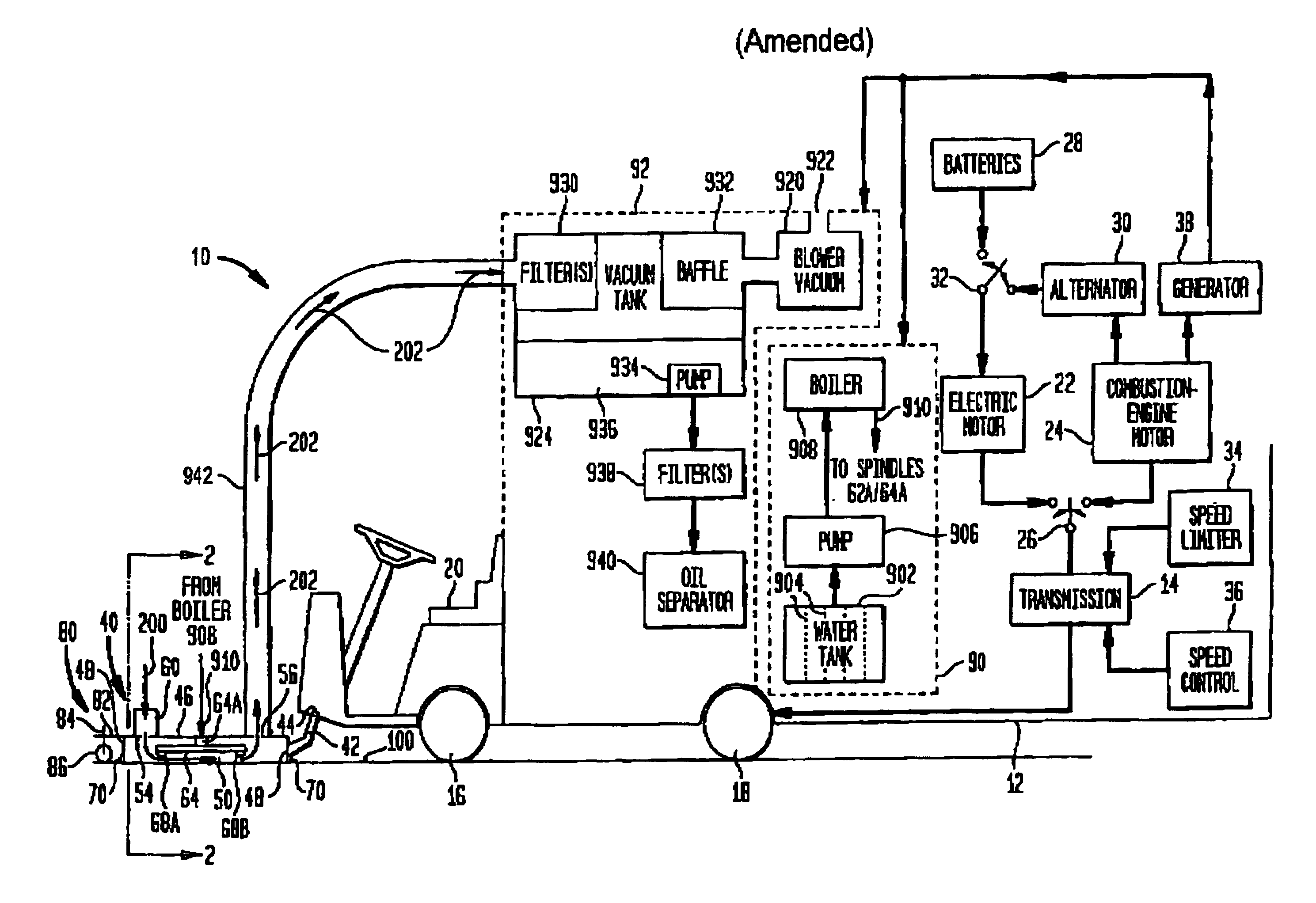
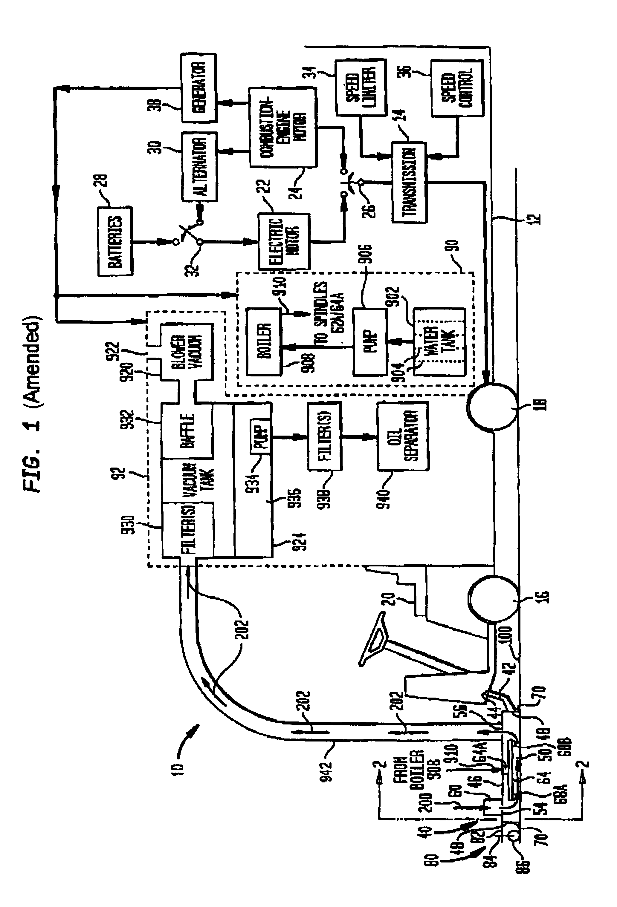
[0023]Referring now to the drawings, and more particularly to FIG. 1, a self-propelled brushless surface cleaner according to the present invention is shown and referenced generally by numeral 10. Surface cleaner 10 is a self-contained assembly for cleaning a surface 100 over which it can be driven. Such surfaces include, but are not limited to, runways, streets, sidewalks, parking surfaces, decks of ships and industrial floor areas.

[0024]Surface cleaner 10 includes a self-propelled vehicle having a frame 12, a drive train coupled to frame 12 that includes a transmission 14 coupled to rear wheels 18 (as shown) and / or front wheels 16. Controls for driving surface cleaner 10 and operating various systems thereon are provided in a driver / operator compartment 20 at the front portion of the vehicle. For reasons that will be explained further below, transmission 14 can be selectively coupled to either an electric motor 22 or a combustion-engine motor 24 via an operator-positioned switch 2...


PUM


Abstract

A self-propelled brushless surface cleaner with reclamation is provided as a self-contained vehicle. A cleaning head mounted to the vehicle extends forward therefrom. The cleaning head has a deck and a skirt extending from the deck such that when the skirt is placed in contact with the surface to be cleaned, a cleaning volume is defined. The cleaning head has at least one vent port formed in a forward portion thereof and at least one vacuum port formed in a rear portion thereof. Nozzles are mounted in the cleaning volume for movement therein when liquid under pressure is supplied thereto and sprayed therefrom. A liquid supply system supplies the liquid under pressure to the nozzles so that the surface to be cleaned is effectively scrubbed by the liquid to produce a mixture of the liquid and contaminants loosened from the surface to be cleaned. A vacuum recycling system coupled to the vacuum port(s) draws high-pressure air through the vent port(s) and over the surface being sprayed with the liquid under pressure. The mixture of liquid and contaminants is suctioned through the rear vacuum port(s) and filtered to separate the liquid from the contaminants. The liquid so-separated is returned to the liquid supply system for reuse thereby.

Description

FIELD OF THE INVENTION[0001]The invention relates generally to surface cleaning apparatus, and more particularly to a self-contained and self-propelled brushless surface cleaner that effectively scrubs a surface with pressurized / heated fluid, and that reclaims both the fluid and contaminants loosened from a surface during the cleaning thereof.BACKGROUND OF THE INVENTION[0002]A variety of industrial-strength surface cleaners are known in the prior art. In general, a pressurized cleaning fluid is sprayed onto a surface to loosen dirt, rubber, oil, grease, etc., that has been deposited on the surface during the use thereof. The loosened dirt and other contaminants are then vacuumed. Some surface cleaners filter out the dirt and other contaminants in order to reuse the cleaning fluid. Specific examples of prior art cleaners are noted below.[0003]U.S. Pat. No. 3,959,010 discloses a surface cleaner having a spray / vacuum head attached to the front of a tractor and having mechanical systems...

Claims


Application Information

Patent Timeline
IPC IPC(8): B08B5/04B08B3/02E01H1/10
CPCB08B3/024B08B5/04B08B2203/0229E01H1/103
Inventor CLEMONS, WILLIAM E.
Owner CLEAN UP AMERICA
Learn More