Magnetic head suspension assembly fabricated with integral load beam and flexure

a technology of load beam and flexure, applied in the direction of magnetic recording, instruments, data recording, etc., can solve the problems of weak pitch, roll and bending stiffness, and achieve the effect of reducing z-heigh

Inactive Publication Date: 2007-01-23
WESTERN DIGITAL TECH INC
View PDF9 Cites 56 Cited by
  • Summary
  • Abstract
  • Description
  • Claims
  • Application Information

AI Technical Summary

Benefits of technology

[0008]An object of this invention is to provide a head suspension and slider assembly having significantly reduced Z-height.

Problems solved by technology

These suspensions are characterized by weak pitch, roll and bending stiffness when the head is flying over the disk surface.

Method used


Image

  • Magnetic head suspension assembly fabricated with integral load beam and flexure
  • Magnetic head suspension assembly fabricated with integral load beam and flexure
  • Magnetic head suspension assembly fabricated with integral load beam and flexure

Examples


Embodiment Construction

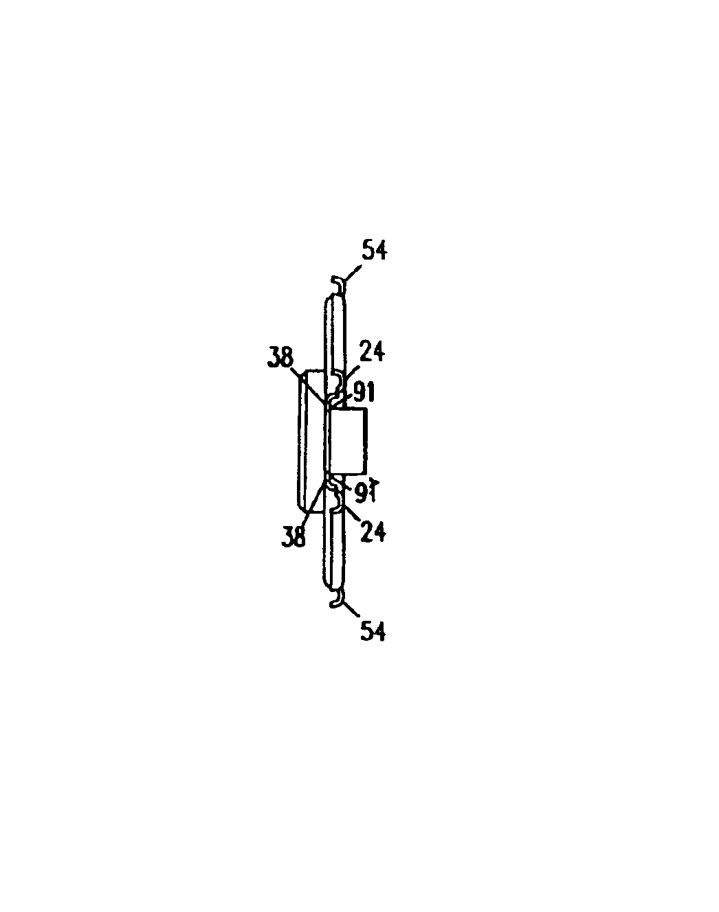
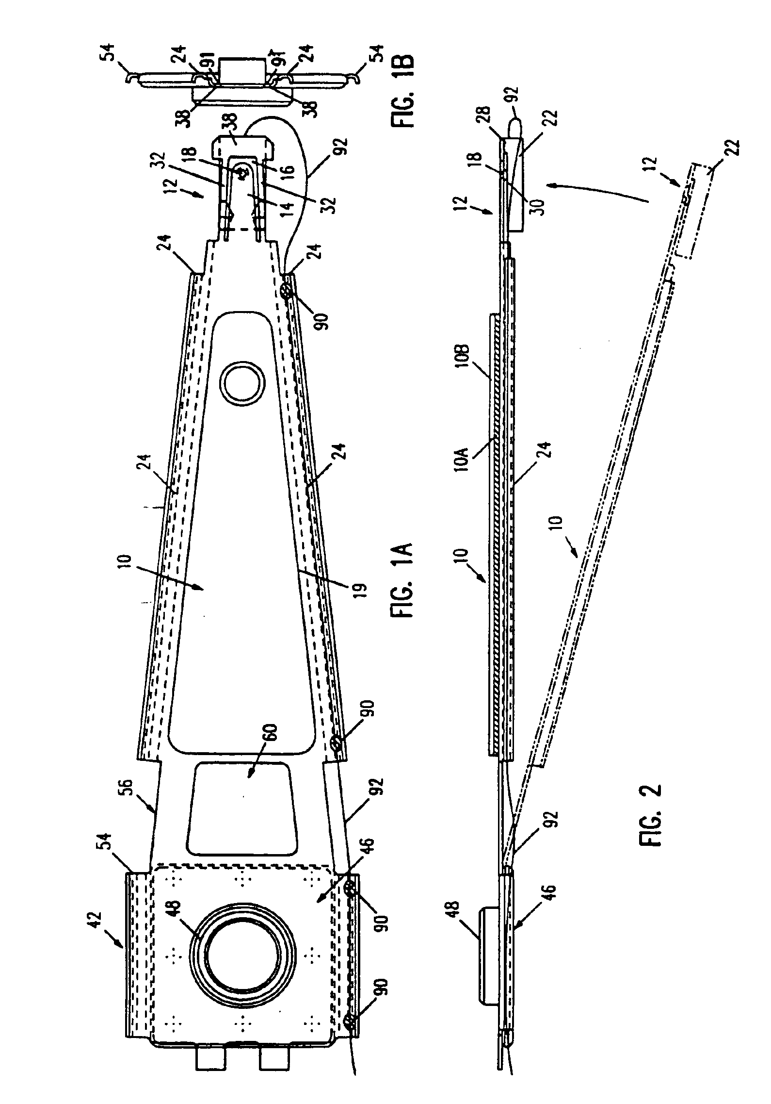
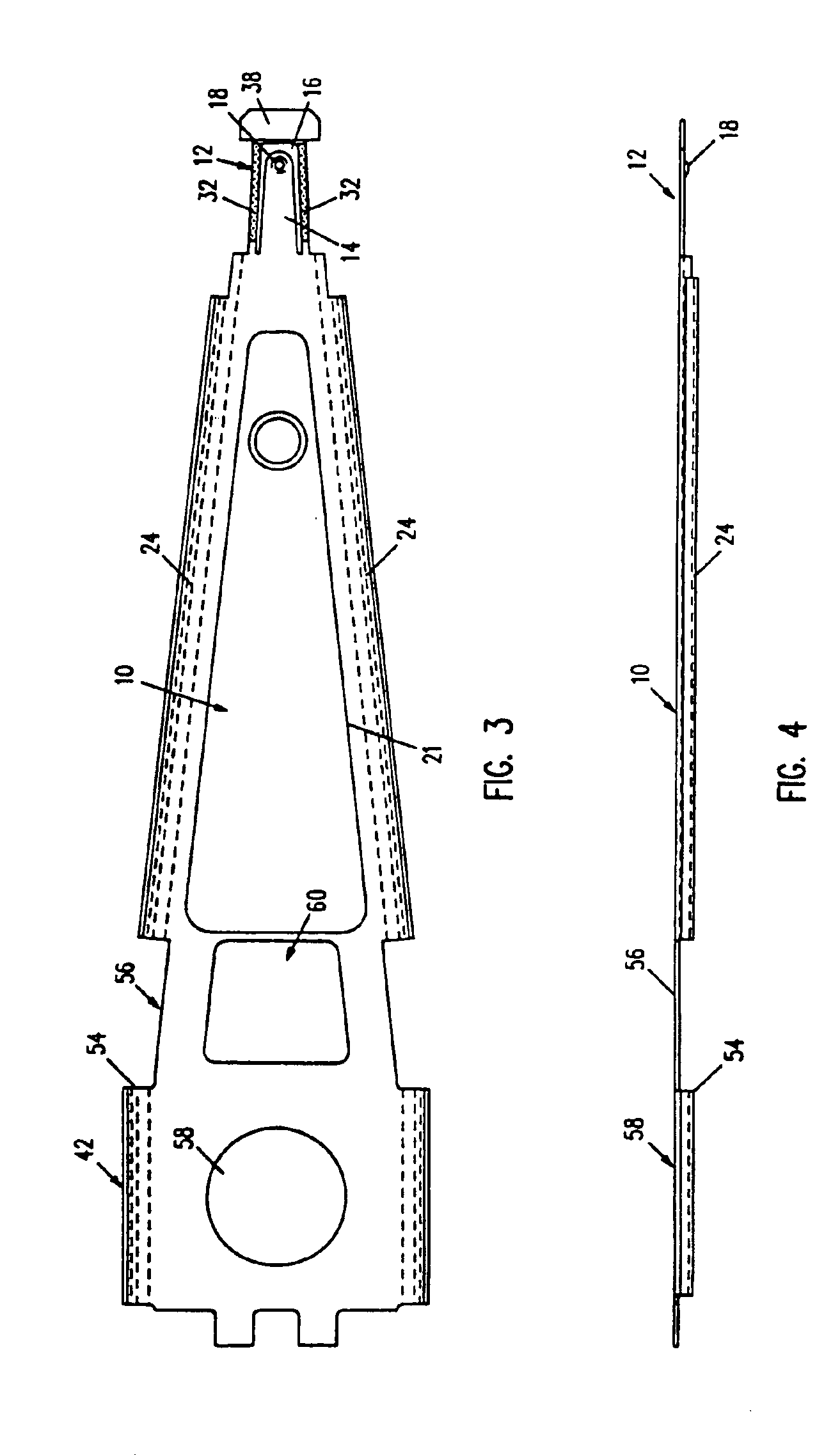
[0037]With reference to FIGS. 1A-5B, a magnetic head suspension assembly includes a load beam section 10, a flexure section 12, a leaf spring section 56 and a rear mount section 42. The suspension is formed from an integral flat piece of nonmagnetic material, preferably a 300 Series type stainless steel having a thickness of about 0.0012 to 0.0013 inch. As a result of using an integral piece, the load beam section 10 and flexure section 12, as well as the leaf spring section 56 and rear mount section 42, are disposed substantially in a single plane. No separate forming of individual load beam and flexure parts is required. Therefore, no assembly steps of joining and welding are needed for attaching the flexure to the load beam.

[0038]The load beam section 10 is preferably made in a truncated conical or triangular shape. The load beam section has a short tapered tongue 14 extending from its relatively narrow end into the flexure section 12. The tongue 14 is delineated by a U-shaped cu...


PUM

PropertyMeasurementUnit
thickaaaaaaaaaa
thickaaaaaaaaaa
thicknessaaaaaaaaaa

Abstract

A magnetic head suspension assembly is fabricated with an integral piece which includes a load beam section, a flexure section, a rest mount section and a leaf spring section between the load beam and rear mount. A tongue extends from the load beam to the flexure and has a down-facing load dimple which contacts the non-air bearing surface of an attached air bearing slider. The flexure includes narrow thin legs adjacent to a cutout that delineates the load beam tongue. The head suspension is characterised by a high first bending mode frequency and low pitch and roll stiffness.

Description

[0001]ThisThe present application is a divisional application of application No. 08 / 521,786 filed Aug. 31, 1995, which is a reissue of application No. 08 / 042,906 filed Apr. 5, 1993, which issued as U.S. Pat. No. 5,282,103 on Jan. 25, 1994, which is a continuation-in-part of application Ser. No. 07 / 938,516, filed Oct. 7, 1992, now abandoned. The present application is related to copending reissue application Nos. 08 / 662,531 and 08 / 662,885, both filed Jun. 13, 1996, and also to copending reissue application No. 10 / 631,993 filed Jul. 30, 2003.CROSS-REFERENCE TO COPENDING APPLICATION[0002]Copending U.S. patent application Ser. No. 07 / 926,033 filed Aug. 5, 1992<?insert-start id="INS-S-00004" date="20070123" ?>, now U.S. Pat. No. 5,299,081 issued on Mar. 29, 1994<?insert-end id="INS-S-00004" ?>, is directed to a head suspension assembly particularly useful with nanosliders, which are about 50% of the size of the standard full size air bearing sliders. The present application...

Claims


Application Information

Patent Timeline
Patent Type & Authority Patents(United States)
IPC IPC(8): G11B5/48G11B21/12G11B21/20G11B21/21
CPCG11B5/4833
Inventor HATCH, MICHAEL R.LEUNG, CHAK M.
Owner WESTERN DIGITAL TECH INC
Why Eureka
Try Eureka