Nozzle arrangement for a paint spray gun

Inactive Publication Date: 2008-07-15
SATA GMBH & CO KG
View PDF6 Cites 38 Cited by
  • Summary
  • Abstract
  • Description
  • Claims
  • Application Information

AI Technical Summary

Benefits of technology

[0007]Thus, it is an object of the invention to provide a nozzle arrangement such that the annular air jet flows out as homogeneously as possible and accidental losses of quality are avoided during production.

Problems solved by technology

A disadvantage of the arrangement described is that the air does not flow uniformly into the annular slot via the supply bores arranged about the periphery inside the nozzle arrangement, as a result of which the air / paint mixture is not distributed as uniformly as possible in the circular jet.
In addition, this arrangement has the disadvantage that the air from the supply bores reaches directly into the control bores for the horn air, depending on the angular position of the paint nozzle having the bores relative to the housing or air cap of the paint spray gun, when the supply bores are about colinear with these control bores and, as a result, the horn air is affected too greatly in an undesirable manner, which in turn changes the jet pattern in an undesirable manner.
However, the position of the paint nozzle screwed into the housing of the paint spray gun is determined by the starting cut of its thread and thus a great extent accidental, so that some of the guns produced exhibit undesirable paint coat properties.

Method used


Image

  • Nozzle arrangement for a paint spray gun
  • Nozzle arrangement for a paint spray gun
  • Nozzle arrangement for a paint spray gun

Examples


Embodiment Construction

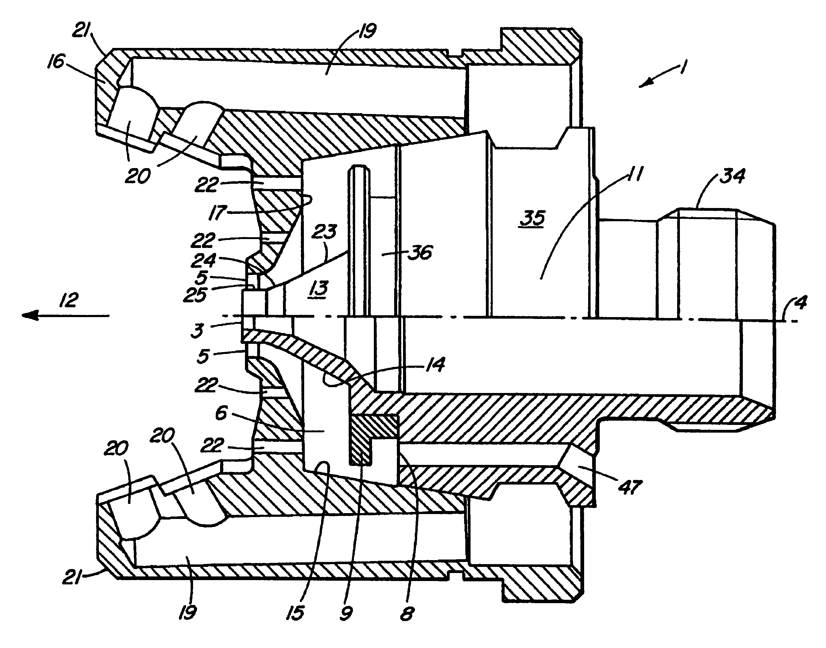
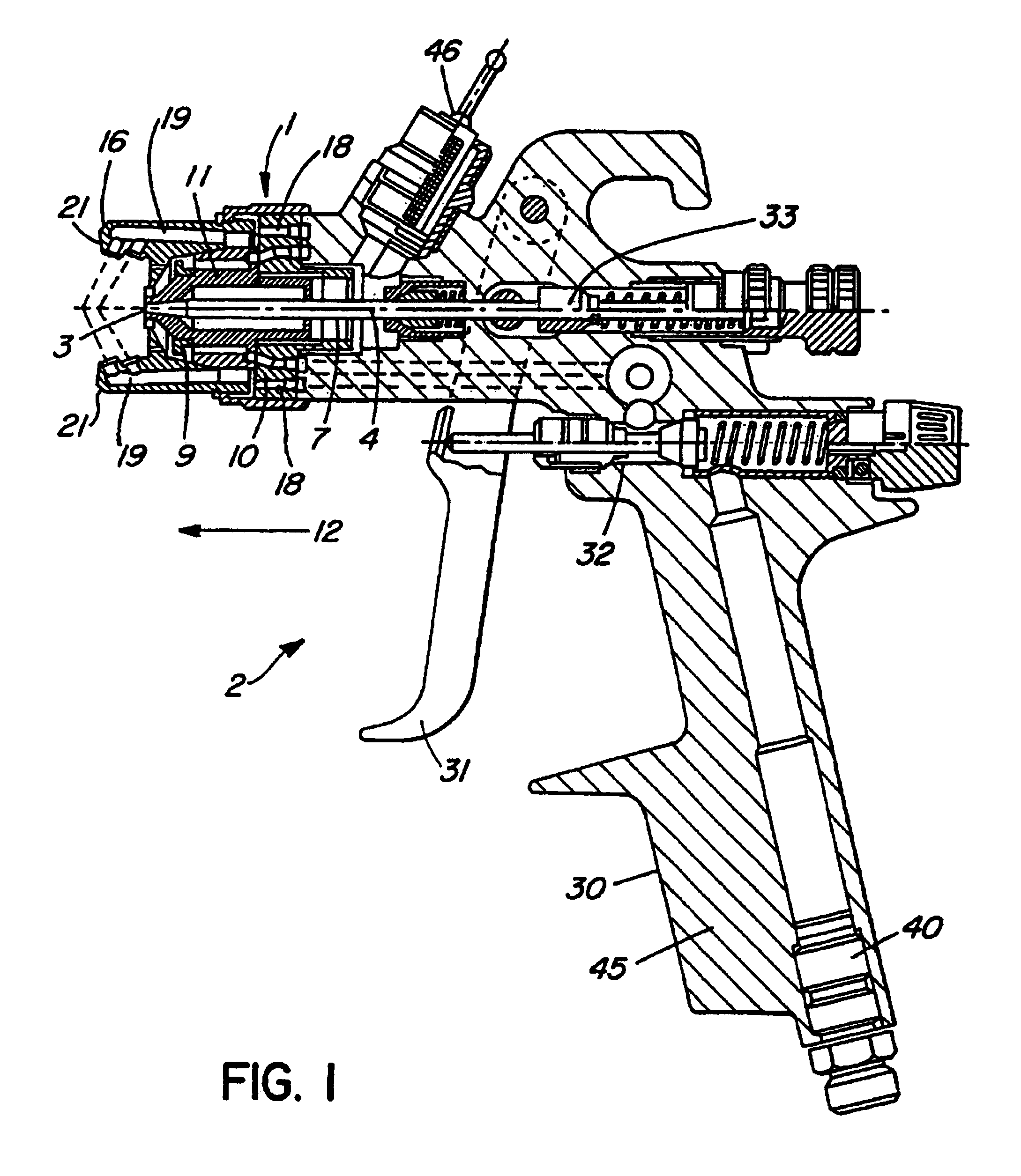
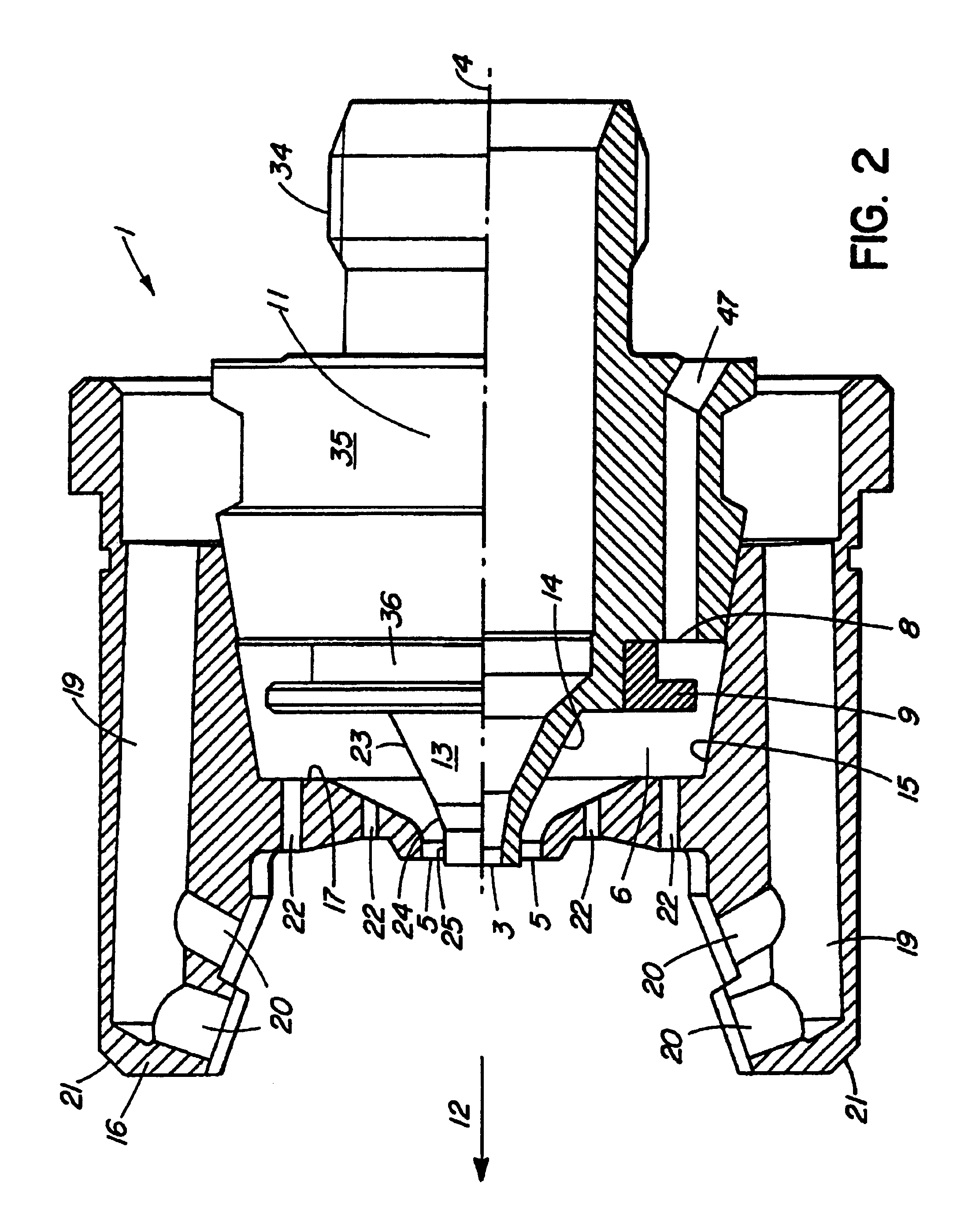
[0012]The paint spray gun shown in the Figure is comprised essentially of a housing 30 which includes an upper part with a suspension hook and a handle 45. A compressed-air supply conduit is attached to the underside of the handle 45, an air choke 40 can be built in to decrease the pressure when the air enters, primarily in low-pressure guns; a fluid container for the paint is mounted on the top at a connection 46. The compressed air (via a valve arrangement 32) and the outlet 3 (via a pin control device 33) are simultaneously released for the paint by means of an operating lever 31. The paint flows from the fluid container (not shown), without pressure support, to the outlet 3 and passes out there when the pin 7 is pulled back. Compressed air flows simultaneously via a conduit system to the annular slot 5 which surrounds the outlet 3 and produces a vacuum directly at the outlet 3. This vacuum sucks paint out of the outlet 3, which is then atomized and carried along due to the quick...


PUM


Abstract

A nozzle structure for a paint spray gun, is comprised of a central outlet for paint, an annular slot surrounding the central outlet, the annular slot being connected inside the nozzle structure via an annular duct to a number of virtually axially parallel bores, the bores being situated on at least one circle about a central axis of the nozzle structure, apparatus for providing, compressed air via the bores for delivery to the annular duct, and an air reversingdeflection disk located inside the annular duct and opposite the bores.

Description

FIELD OF THE INVENTION[0001]The invention relates to a nozzle arrangement for a paint spray gun, as well as the paint spray gun.BACKGROUND TO THE INVENTION[0002]A nozzle arrangement for a paint spray gun is described in German Utility Model G 90 01 265.8. The nozzle arrangement described in that document has a central outlet for the paint which can be closed with an axially extending pin. The paint flows pressureless from a fluid container to this sealable outlet. The outlet is surrounded by an annular slot out of which a circular air jet of high velocity flows, which thereby sucks paint out of the outlet, atomizes it and carries it along, as a result of which a circular jet consisting of paint particles is formed.[0003]Laterally of the jet direction, the nozzle arrangement has two protruding horns, horn air jets of which are directed diagonally and in the same direction to the direction of flow of and into the circular jet, which deformed it. To control the horn air, the nozzle arr...

Claims


Application Information

Patent Timeline
IPC IPC(8): B05B7/04B05B1/06B05B1/28B05B7/08B05B7/12
CPCB05B7/0815B05B7/1209
Inventor SCHMON, EWALD
Owner SATA GMBH & CO KG
Why Eureka
Try Eureka