Machine tool center

a machine tool and center technology, applied in the field of machine tool centers, can solve the problems of endangering the operator, the other machine tools in the machine tool center cannot be served by the loading device, etc., and achieve the effect of improving the functional reliability of the machine tool and increasing the work safety of the operator

Inactive Publication Date: 2009-03-31
CHIRON WERKE
View PDF12 Cites 4 Cited by
  • Summary
  • Abstract
  • Description
  • Claims
  • Application Information

AI Technical Summary

Benefits of technology

[0010]In view of the above it is an object of the present invention to improve the known machine tool center such that it can be better used with a less complicated construction whereby an increased work safety for the operator and improved functional reliability of the machine tool are to be achieved.

Problems solved by technology

However, this also means that the other machine tools in the machine tool center can no longer be served by the loading device if the safety of the operator is given priority.
In other words, as long as the operator is busy with one of the machine tools through the operator door the appliance cannot move the loading device past this machine tool without endangering the operator.

Method used


Image

  • Machine tool center
  • Machine tool center
  • Machine tool center

Examples


Embodiment Construction

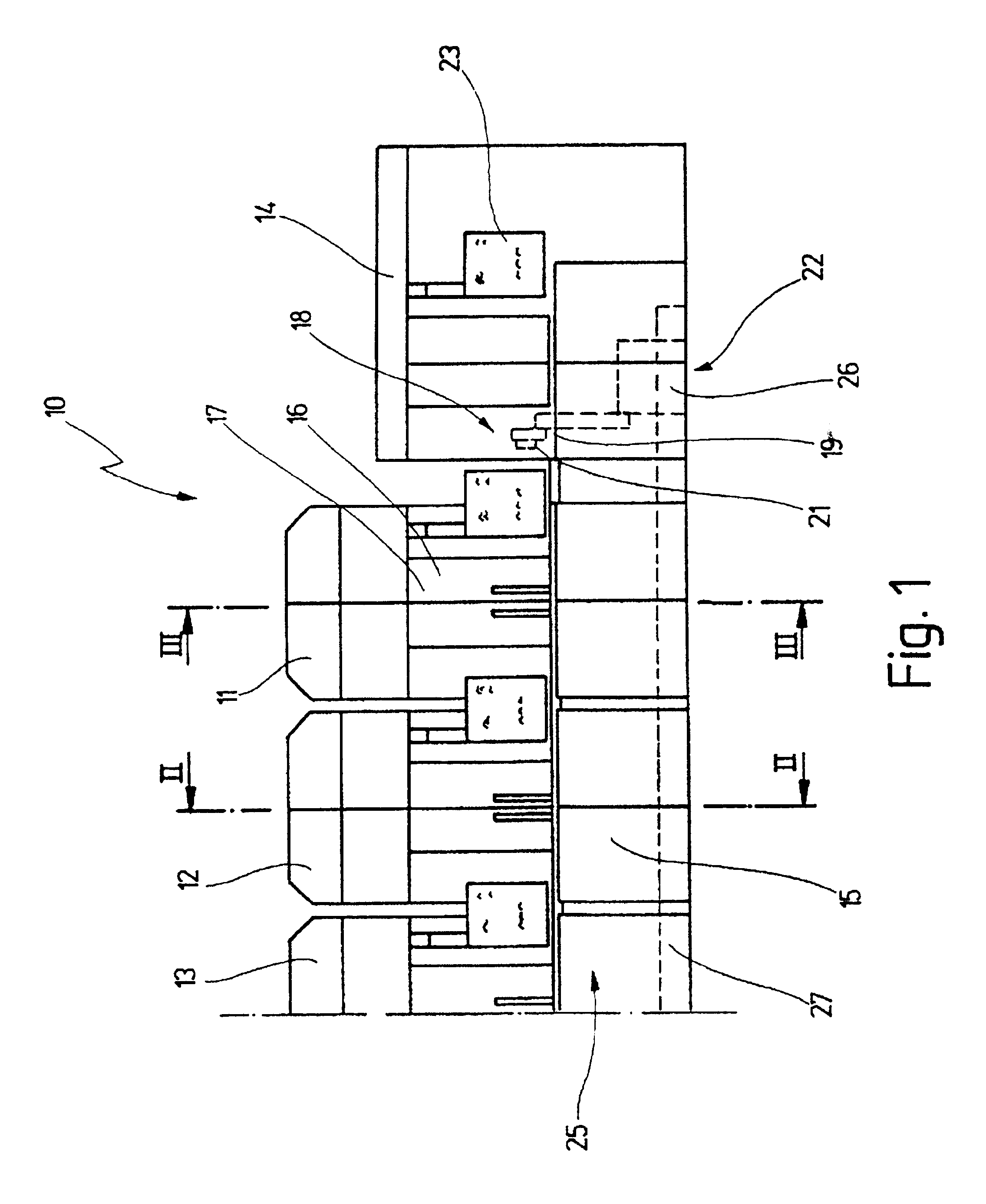
[0045]FIG. 1 shows the front view of a machine tool center 10 in which the machine tools 11, 12 and 13 (only indicated) are arranged alongside one another. These machine tools 11, 12, 13 can either be arranged in a straight line or circle. A loading / unloading station 14 is provided in addition to the machine tools 11, 12, 13.

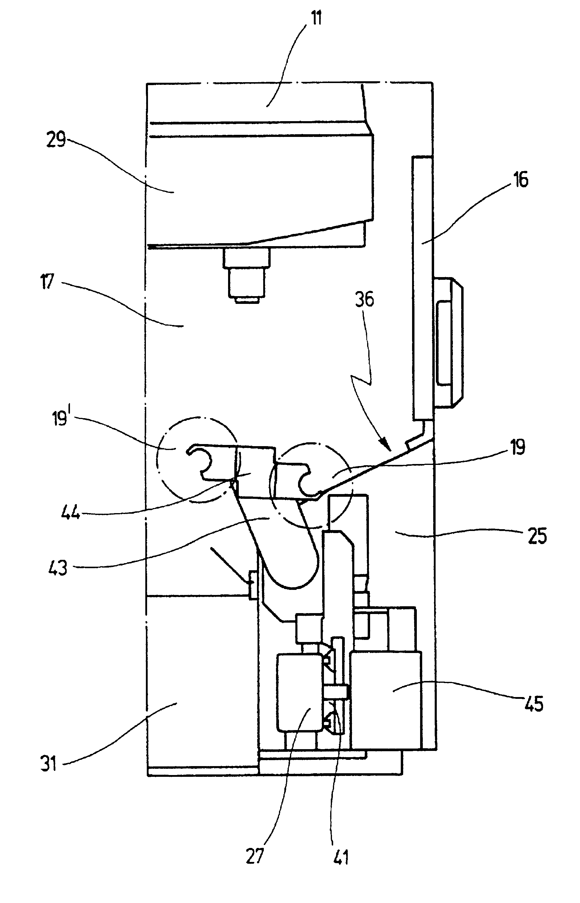
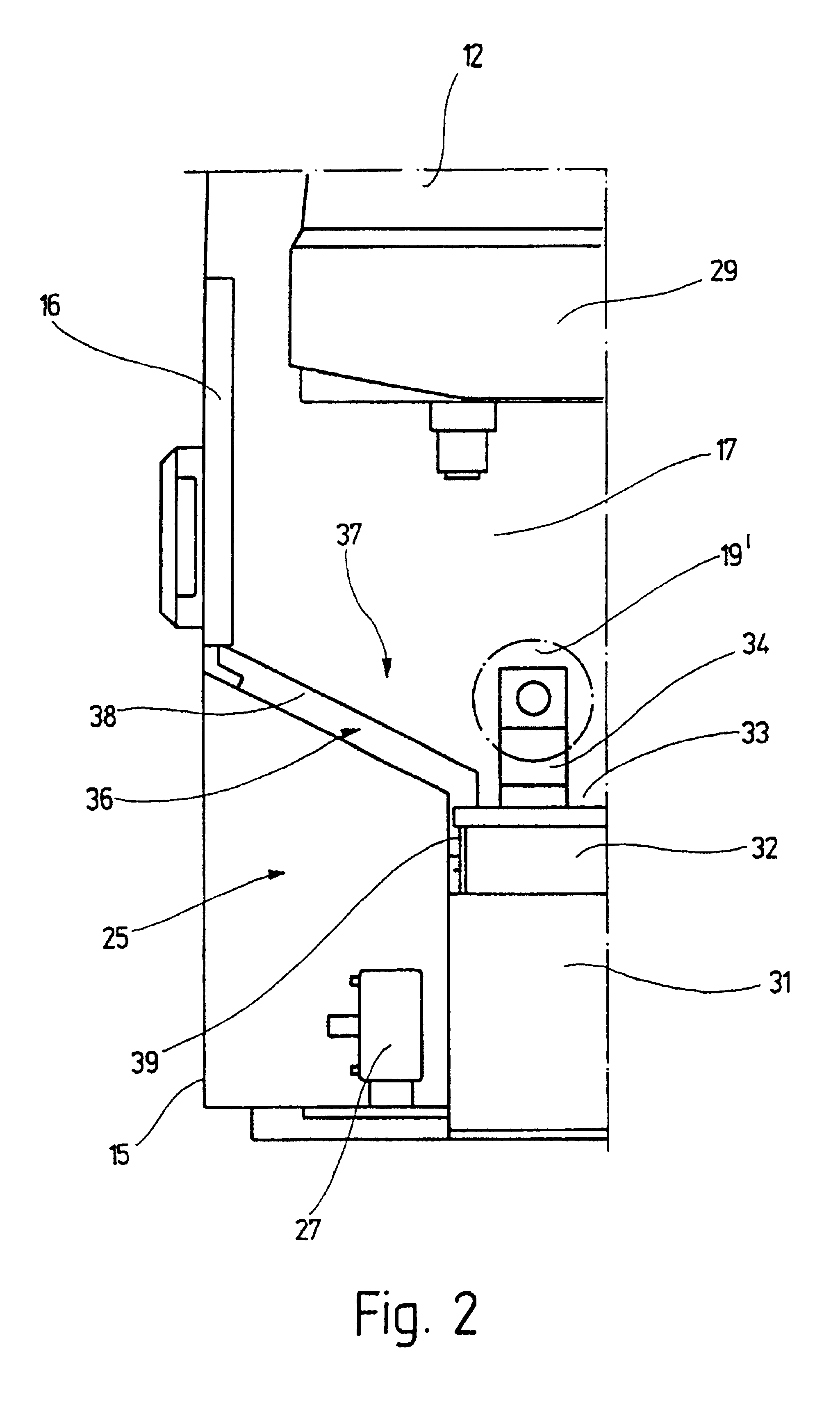
[0046]The machine tools 11, 12, 13 display a casing 15 which completely surrounds them and in which there is an operator door 16 for each machine tool 11, 12, 13 through which an operator has access to the working space 17. Set-up and service work is carried out for the individual machine tools 11, 12, 13 through this operator door 16.

[0047]A clamping station 18, shown only diagrammatically, is provided in the loading / unloading station 14 in which individual workpiece holders 19 are provided with workpieces 21 to be processed. The workpiece holders 19 provided with workpieces 21 in this manner are transported to the individual machine tools 11, 12, 13 by means o...


PUM


Abstract

A machine tool center (10) displays at least one machine tool (11, 12, 13) which has a working area (17) accessible through an operator door (16) to process workpieces (21). Furthermore, a loading/unloading station (14) for the workpieces (21) and a loading device (22) which transports the workpieces (21) between the loading/unloading station (14) and the respective machine tool (11, 12, 13) and changes these at the machine tool (11, 12, 13) are also provided. In the new machine tool center (10) the loading device (22) is arranged below the working space (17) of the machine tool (11, 12, 13) (FIG. 1).

Description

[0001]This application is a continuation of U.S. application Ser. No. 08 / 641,508, filed May 1, 1996, now U.S. Pat. No. 5,871,326.BACKGROUND OF THE INVENTION[0002]The present invention relates to a machine tool center with at least one machine tool which has a working space accessible through an operator door to process workpieces, a loading / unloading station for the workpieces and a loading device which transports the workpieces between the loading / unloading station and the respective machine tool and changes these at the machine tool.[0003]1. Field of the Invention[0004]Such machine tool centers are generally known.[0005]2. Related Prior Art[0006]In the known machine tool centers the loading devices are arranged in front of the respective machine tools which are installed alongside one another either in a straight line or in a circle. The loading device displays an appliance which moves back and forth between the loading / unloading station and the respective machine tool and hereby ...

Claims


Application Information

Patent Timeline
Patent Type & Authority Patents(United States)
IPC IPC(8): B65H5/08B23P23/00B23Q7/00B23Q7/04B23Q7/14B23Q11/08B23Q41/04B23Q41/08G05B19/418
CPCB23Q7/04B23Q7/1405B23Q11/08B23Q41/08
Inventor HANINGER, RUDOLFWINKLER, HANS-HENNING
Owner CHIRON WERKE
Why Eureka
Try Eureka