Oscillatory chest compression device

Inactive Publication Date: 2009-06-30
HILL ROM SERVICES
View PDF145 Cites 23 Cited by
  • Summary
  • Abstract
  • Description
  • Claims
  • Application Information

AI Technical Summary

Benefits of technology

[0008]The present invention is directed to an oscillatory chest compression device that loosens and assists in expulsion of secretions in a person's lungs. A vest, containing a bladder, is secured to a patient's upper torso. One or more tubes connect the bladder with a generator. The generator includes a first, o

Problems solved by technology

Currently there is no cure for cystic fibrosis.
This daily treatment may take several hours and requires a trained individual to apply the pounding treatment.
Vibrators and other direct mechanical compression devices are likely to be heavier than pneumatic compressi

Method used


Image

  • Oscillatory chest compression device
  • Oscillatory chest compression device
  • Oscillatory chest compression device

Examples


Embodiment Construction

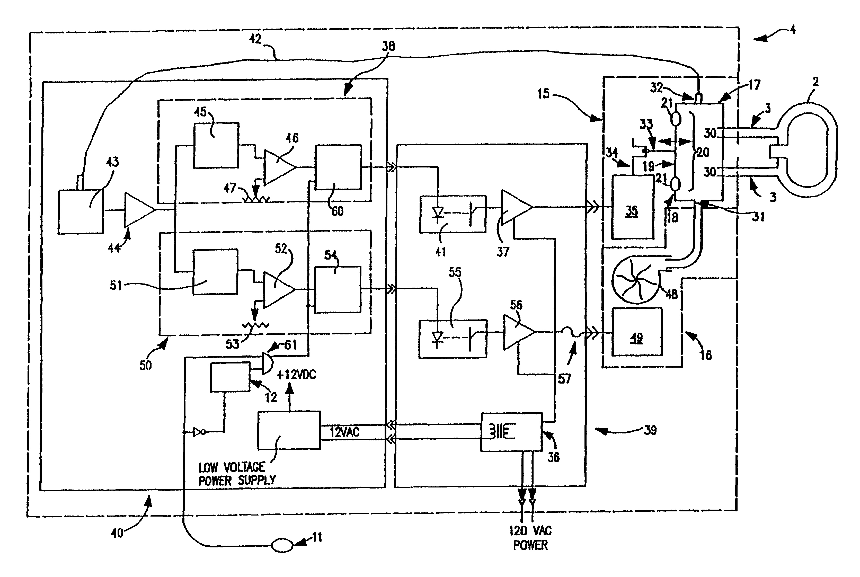
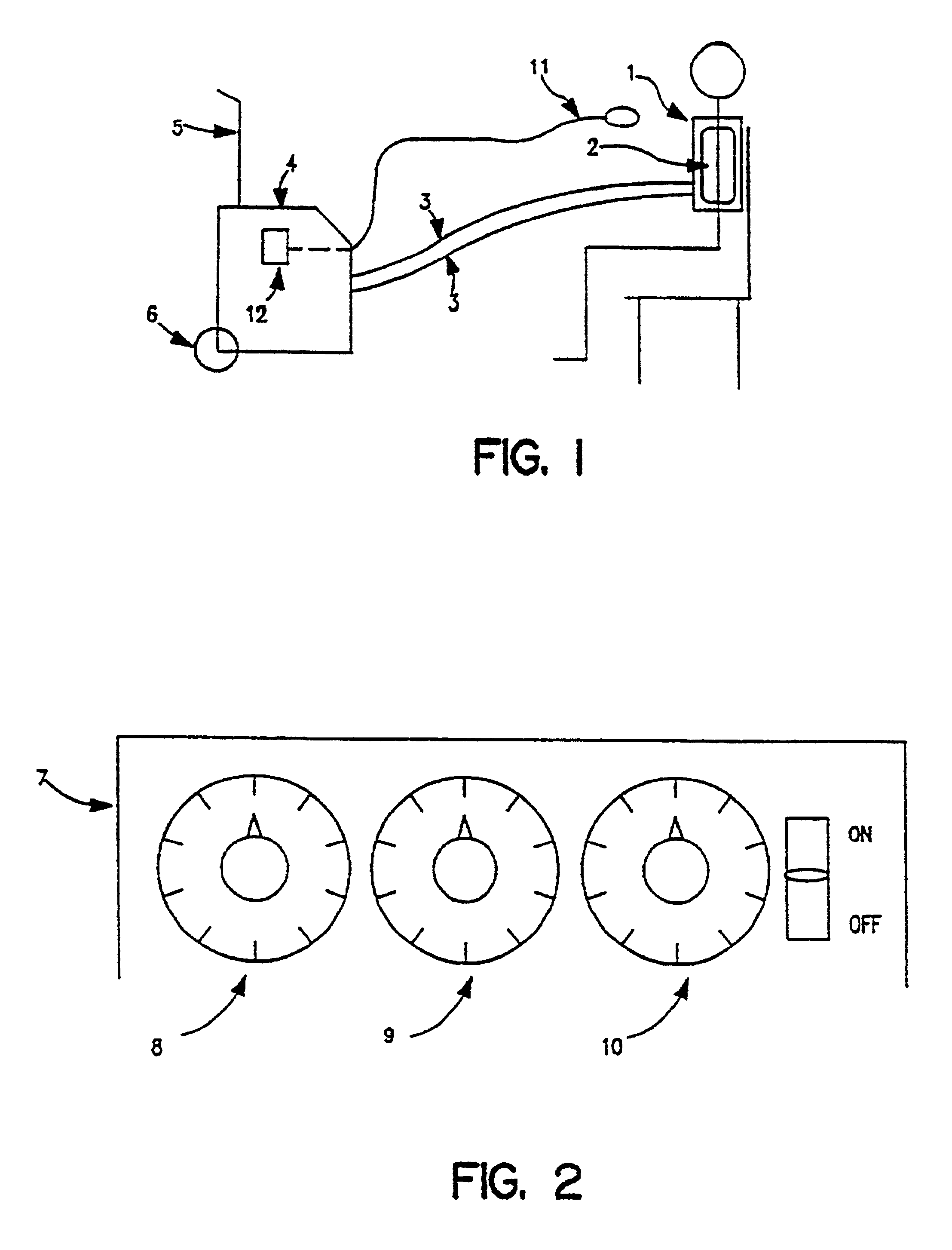
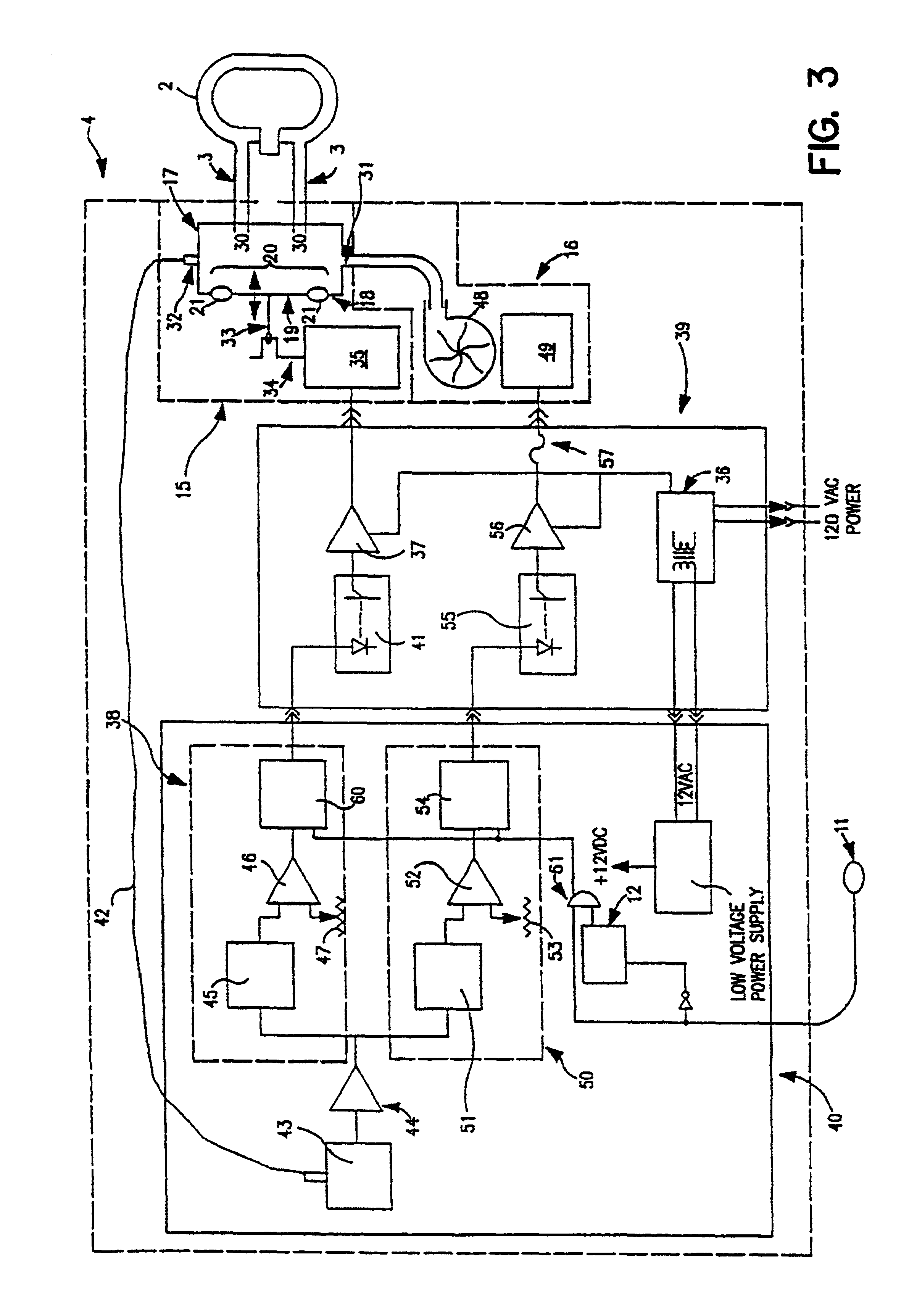
[0019]A chest compression device is shown in FIG. 1. A vest 1 is secured about the torso of a patient. A bladder 2 is fitted within vest 1. Oscillatory air pulses are delivered to bladder 2. The outer surface of vest 1 is made of a non-stretch material, causing the expansions and contractions of bladder 2 to occur generally adjacent the patient's torso. The expansions and contractions create a pneumatic, oscillatory compression of the patient's torso to loosen and assist the expulsion of mucous and other secretions in the patient's lungs. Suitable vests are available from American Biosystems, Inc., St. Paul, Minn., the assignee of the present invention.

[0020]Tubes 3 connect bladder 2 with generator 4. Two tubes 3 are shown in FIGS. 1 and 3; however, the number of tubes 3 may be varied depending on the desired operating parameters of bladder 2. Generator 4 generates oscillatory air pulses in accordance with user-selected settings. The pulses are converted into compressions of the pat...


PUM


Abstract

An oscillatory chest compression device includes an oscillatory air flow generator and a positive air flow generator. A first feedback system controls the oscillation rate of the oscillatory air flow generator, and a second feedback system controls the peak pressure created by the positive air flow generator.

Description

[0001]This is a continuation of application Ser. No. 08 / 661,931, filed Jun. 11, 1996, now U.S. Pat. No. 5,769,797.FIELD OF THE INVENTION[0002]The present invention relates to an oscillatory chest compression device.BACKGROUND OF THE INVENTION[0003]Certain respiratory disorders, such as cystic fibrosis, emphysema, asthma, and chronic bronchitis, may cause mucous and other secretions to build up in a person's lungs. It is desirable, and sometimes essential, that the secretion build-up be substantially removed from the lungs to enable improved breathing. For example, Cysticcystic fibrosis is an hereditary disease that affects the mucous secreting glands of a person, causing an excessive production of mucous. The mucous fills in the person's lungs and must be reduced daily to prevent infection and enable respiration by the person.[0004]Currently there is no cure for cystic fibrosis. Current treatment of cystic fibrosis includes an aerosol therapy to assist lung drainage and repeated pou...

Claims


Application Information

Patent Timeline
IPC IPC(8): A61H31/00A61H23/04
CPCA61H9/0078A61H2205/08Y10S601/11
Inventor VAN BRUNT, NICHOLAS P.GAGNE, DONALD J.
Owner HILL ROM SERVICES
Why Eureka
Try Eureka