Temperature compensated high power bandpass filter

a bandpass filter and temperature compensation technology, applied in the field of electromagnetic signal communication, can solve the problems of not meeting requirements, many electronic filters do not have the capacity for such large signal power, and the fcc emission mask for digital television broadcast stations is very restrictive, so as to minimize any drift in the resonant frequency

Inactive Publication Date: 2009-09-01
ELECTRONICS RES
View PDF16 Cites 2 Cited by
  • Summary
  • Abstract
  • Description
  • Claims
  • Application Information

AI Technical Summary

Benefits of technology

[0007]In accordance with the present invention, a bandpass filter is provided that uses the deformation of a cavity surface in response to thermal changes to compensate for the resonant frequency shifting effects of thermal expansion. The filter has at least one waveguide cavity in which an input electrical signal resonates at a desired resonant frequency, and a plurality of surfaces, each with a predetermined geometric shape. For example, in a preferred embodiment, the filter has a cylindrical outer surface and a circular end plate. A thermal compensator is provided that responds to thermally induced changes in dimensions of the cavity by distorting the shape of one of the cavity surfaces, thereby minimizing any resulting drift in the resonant frequency.
[0008]Typically, the thermally induced changes in the cavity are an increase in cavity dimensions, and the thermal compensator deflects one of the cavity surfaces inward, such as in the case of a concave deflection of the cavity end plate. In the preferred embodiment, the thermal compensator includes a control rod that limits the movement of at least a first point on an end plate of the cavity in a first direction. That is, the control rod prevents movement of that point in the direction of thermal expansion. Thus, as the cavity expands, outer portions of the end plate move in the direction of the expansion, but the first point is restricted by the control rod. As a result, the end plate is deformed from its original shape. The control rod has a coefficient of thermal expansion that is significantly different (typically lower) than that of a material from which the cavity is constructed.
[0010]In determining the appropriate amount that a cavity surface point should be deflected, a theoretical model may be used to first establish how far a movable end plate would have to be moved to compensate for an expansion of the waveguide cavity without the end plate being distorted. The resulting deflection distance may then be augmented to compensate for the fact that, in the present invention, the entire surface is not being moved. This additional deflection may be determined empirically, and can provide a more accurate compensation for control of the cavity resonant frequency.

Problems solved by technology

Many electronic filters do not have the capacity for such large signal powers.
The FCC emissions mask for digital television broadcast stations is very restrictive for power radiated into adjacent channels or out-of-band frequencies.
These requirements will not be satisfied by filters that have wide pass-bands that are allowed to drift.
However, this tuning mechanism requires a manual adjustment of a screw device to make the necessary changes.
As such, the cavity is unsealed, and is prone to leakage and poorer performance than a sealed filter.
However, Invar is also very expensive, and consequently drives up the overall cost of the filter.

Method used


Image

  • Temperature compensated high power bandpass filter
  • Temperature compensated high power bandpass filter
  • Temperature compensated high power bandpass filter

Examples


Embodiment Construction

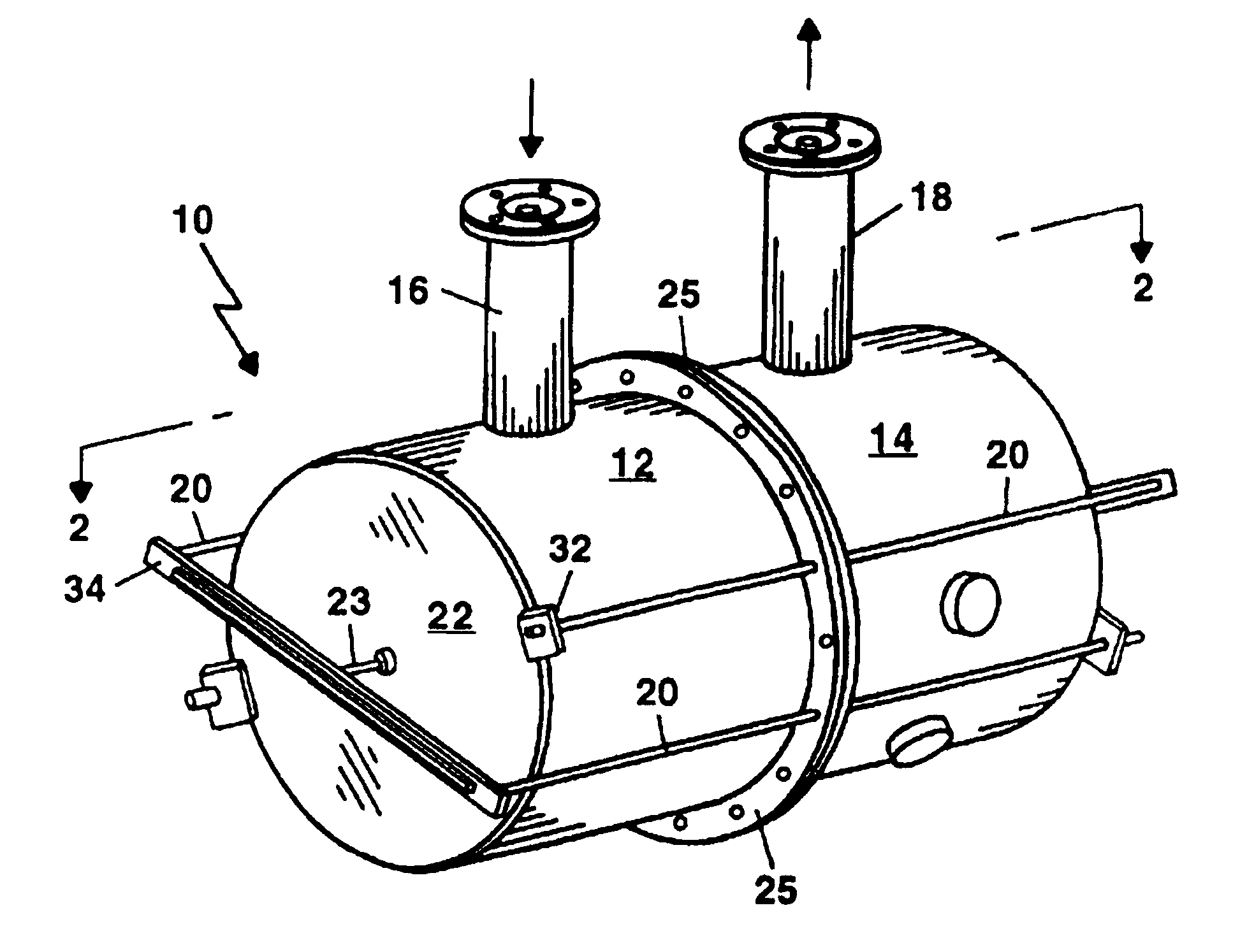
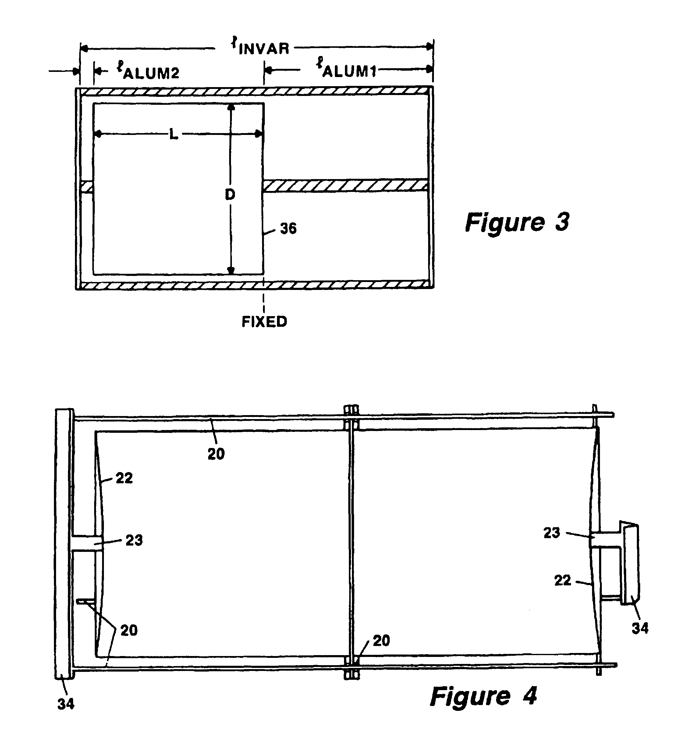
[0017]Shown in FIG. 1 is a perspective view of a temperature compensated pseudo-elliptical function mixed mode bandpass filter 10. The filter of FIG. 2 is particularly suitable for high power broadcast applications, and has an aluminum TE11 cavity consisting of cavity portion 12 and cavity portion 14. The filter 10 also has an input stage 16 containing a coaxial resonator, and an output stage 18 containing a coaxial resonator. The filter uses a set of thermal control rods to control the position of the center point of each of two cavity end plates 22 relative to an opposite end of the cylindrical cavity housing. This causes the end plates 22 to deflect when the aluminum cavity housing expands, thereby minimizing thermal drift of the filter pass band due to dimensional changes of the filter cavities.

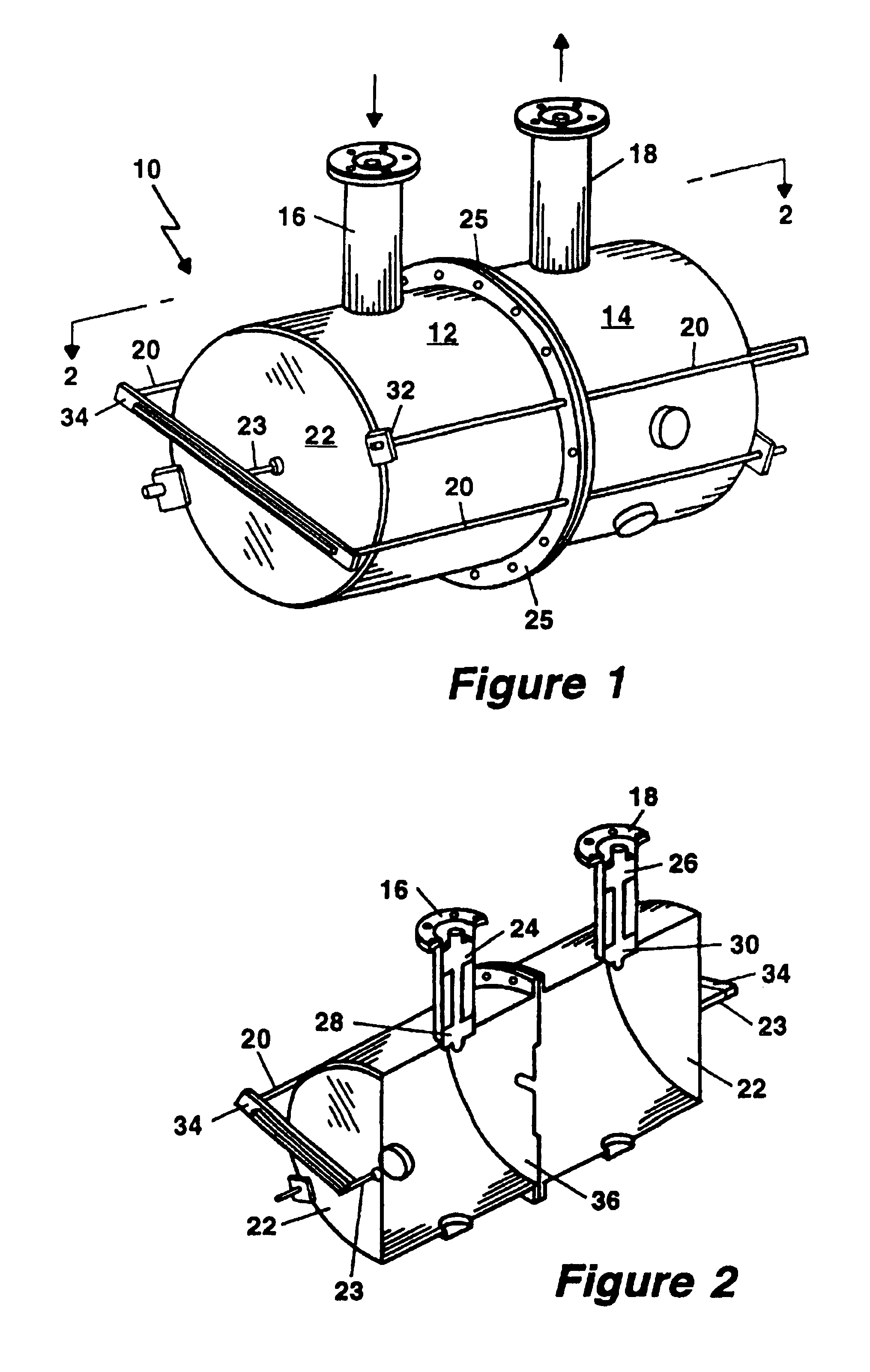
[0018]The filter 10 is shown in cross section in FIG. 2. A coaxial cable (not shown) is connected to filter input stage 16 to allow signal input to the filter. Likewise, the filter output...


PUM


Abstract

A bandpass filter makes use of at least one waveguide cavity that is thermally compensated to minimize drift of a resonant frequency of the cavity with thermal expansion of cavity components. The compensation relies on deformation of the shape of at least one cavity surface in response to thermally-induced dimensional changes of the cavity. A control rod is used to limit the movement of a point on the deformed surface, while the rest of the surface moves with the thermal expansion. The control rod is made of a material having a coefficient of thermal expansion that is significantly different than that of other filter components. The rod may also be arranged to span more thermally expandable material than defines the filter such that, as the filter expands, the point of deflection is moved toward the interior of the filter beyond its original position. A similar effect may be accomplished by connecting the control rod to an end deflecting rod that does the actual limiting of the movement of the deflection point. If the end deflecting rod has a coefficient of thermal expansion that is higher than that of the control rod, the end deflecting rod will expand with temperature relative to the end of the control rod, forcing the deflection point inward.

Description

FIELD OF THE INVENTION[0001]The invention relates generally to the field of electromagnetic signal communication and, more particularly, to the filtering of high power signals for broadcast communications.BACKGROUND OF THE INVENTION[0002]In the field of broadcast communications, electrical filters are required to separate a desired signal from energy in other bands. These bandpass filters are similar to bandpass filters in other fields. However, unlike most other electrical bandpass filters, filters for broadcast communication must be capable of handling a relatively high input power. For example, a signal input to a broadcast communications filter might have an average power between 5 and 100 kilowatts (kW). Many electronic filters do not have the capacity for such large signal powers.[0003]For many years, high power electrical bandpass filtering has included the use of waveguide cavity filters. In particular, the introduction of dual-mode cavities for microwave filters in 1971 mad...

Claims


Application Information

Patent Timeline
Patent Type & Authority Patents(United States)
IPC IPC(8): H01P1/20H01P7/00H01P7/06H01P1/208
CPCH01P1/208
Inventor SMALL, DEREK J.LUNN, JOHN A.
Owner ELECTRONICS RES
Why Eureka
Try Eureka