Transmission power controller

a technology of transmission power controller and output power, which is applied in the direction of gain control, simultaneous amplitude and angle modulation, modulation, etc., can solve the problems of output power, output power, output power change due to drift, maximum 5 db or more drift in transmission power, etc., and achieve the effect of minimizing drift in transmission power

Active Publication Date: 2011-11-22
PANASONIC CORP
View PDF18 Cites 2 Cited by
  • Summary
  • Abstract
  • Description
  • Claims
  • Application Information

AI Technical Summary

Benefits of technology

[0010]It is therefore an object of the present invention to provide a transmission apparatus capable of minimizing drift in transmission power (discontinuity in output power step) due to mode switching between inherently accurate mode 1 (such as compressed mode) and inherently less accurate mode 2 (such as noncompressed mode) during transmission power control.

Problems solved by technology

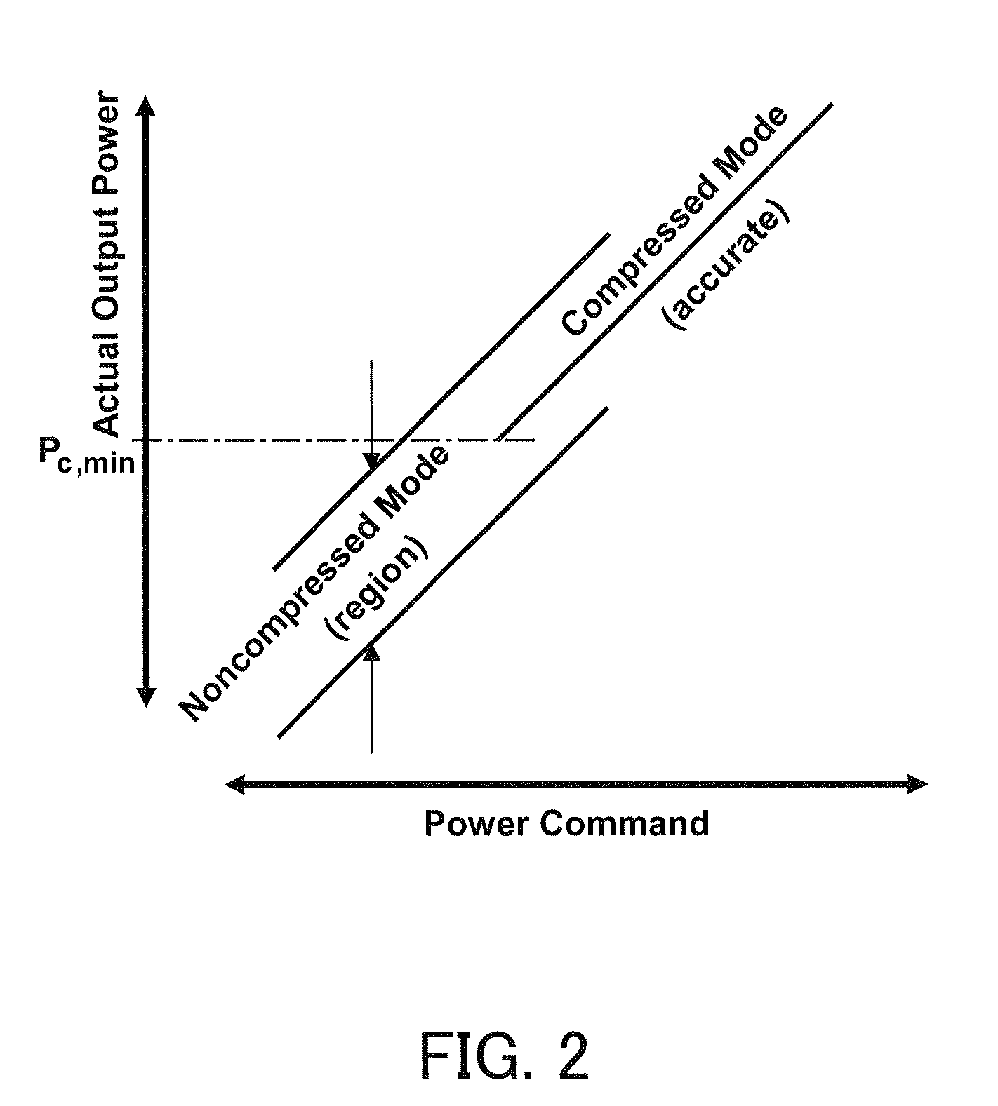
However, with related art transmission apparatus, there is a threat that, when compressed mode (“c-mode”) and noncompressed mode (“n-mode”) switch in transmission power control, drift of maximum 5 dB or more occurs in transmission power due to differences in characteristics between the modes (drift due to temperature, drift due to wear, drift due to load, etc.).
On the other hand, output power of noncompressed mode changes due to drift due to temperature, drift due to wear, drift due to load, etc.
As shown in FIG. 2, output power of noncompressed mode tends to drift due to various factors and therefore is likely to be discontinuous when compressed mode and noncompressed mode switch.
As a result, large drift in transmission power is likely to occur.
With related art transmission apparatus, however, it is difficult to fulfill these requirements provided in 3GPP 25.101, when compressed mode and noncompressed mode switch.

Method used


Image

  • Transmission power controller
  • Transmission power controller
  • Transmission power controller

Examples


Embodiment Construction

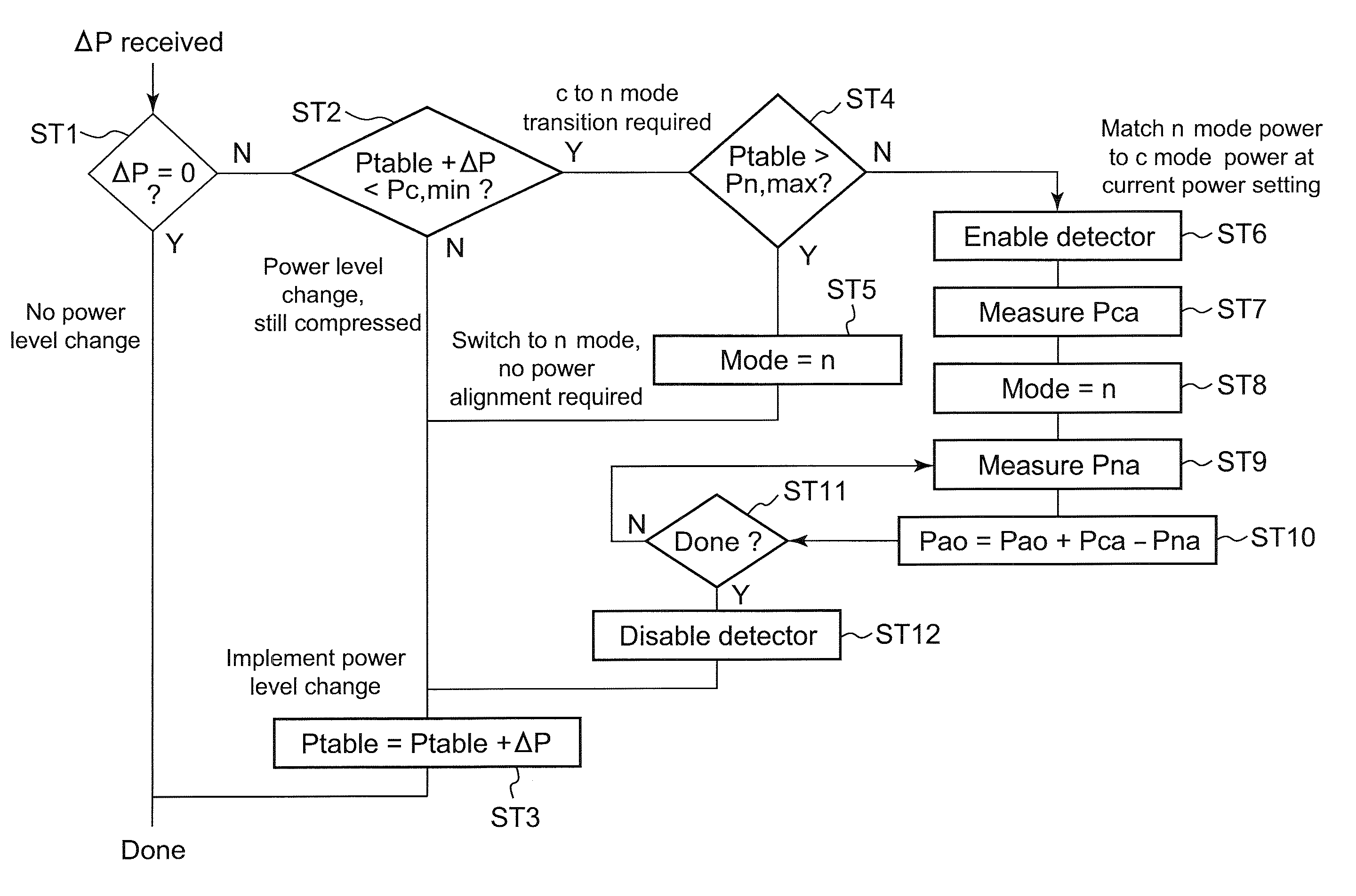
[0039]Now, embodiments of the present invention will be explained in detail below with reference to the accompanying drawings. Reference will now be made in detail to the presently non-limiting, exemplary and preferred embodiments of the invention as illustrated in the accompanying drawings. The nature, concepts, objectives and advantages of the present invention will become more apparent to those skilled in the art after considering the following detailed description in connection with the accompanying drawings. The following description is provided in order to explain preferred embodiments of the present invention, with the particular features and details shown therein being by way of non-limiting illustrative examples of various embodiments of the present invention. The particular features and details are presented with the goal of providing what is believed to be the most useful and readily understood description of the principles and conceptual versions of the present invention...


PUM


Abstract

A transmission apparatus has two modes of power amplifier operation, in which mode 1 is inherently accurate, mode 2 is inherently less accurate, and measurement of a power amplifier output from mode 1 is used to correct a power amplifier output in mode 2. Mode 1 may be a compressed mode and mode 2 may be a non-compressed mode. The apparatus may include a power controller that provides overlapping scaling factor sets for modes 1 and 2 and controls transmission power using the scaling factor sets. Upon a mode transition, the controller uses the overlapping scaling factors and changes the scaling factor set for the mode of a destination of the transition based on actual measurement representative of transmission power, for example, by carrying out power alignment loop operations. A cellular mobile device may include such transmission apparatus. A polar modulation transmitter is also disclosed.

Description

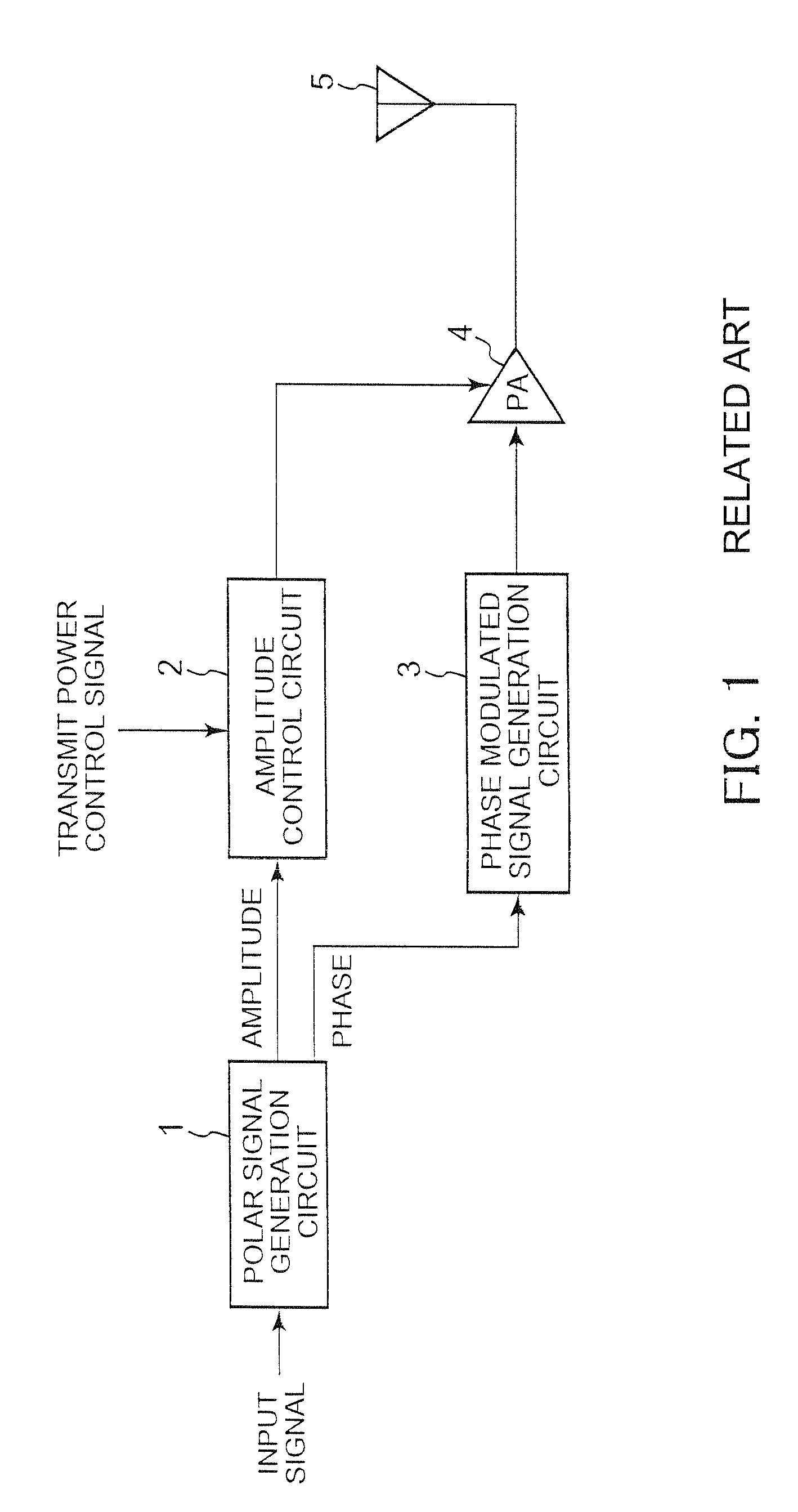
BACKGROUND OF THE INVENTION[0001]1. Field of the Invention[0002]The present invention relates to a transmission apparatus using a power amplifier (hereinafter “PA”).[0003]2. Description of the Related Art[0004]FIG. 1 shows an example of a related art transmission apparatus using polar modulation scheme. The transmission apparatus is provided with a polar signal generation circuit 1, an amplitude control circuit 2, a phase modulated signal generation circuit 3 and a PA 4. In this transmission apparatus, the polar signal generation circuit 1 generates a signal in accordance with the amplitude and phase of a transmit modulated signal from an input signal, and, based on this signal, the amplitude control circuit 2 and the phase modulated signal generation circuit 3 generate the power supply to PA 4 and a phase modulated signal, respectively.[0005]In practice, the transmission apparatus maintains the dynamic range of transmission power by switching the PA 4 between compressed mode and no...

Claims


Application Information

Patent Timeline
Patent Type & Authority Patents(United States)
IPC IPC(8): H04B1/04
CPCH03C5/00H03F1/0205H03F1/0211H03F1/0222H03F3/24H03G3/3042H04B1/0475H03F2200/105H03F2200/324H03F2200/451H03F2200/465H03F2200/504
Inventor MCCUNE, EARLDO, GARYLEE, WAYNE
Owner PANASONIC CORP
Why Eureka
Try Eureka