Removable gas/liquid separator for a motor

a gas/liquid separator and motor technology, applied in the direction of dispersed particle separation, cleaning equipment, separation processes, etc., can solve the problems of affecting the operation of the motor, the nut is a relatively small part, and the overextended shaft is more easily bent and may tend to vibra

Inactive Publication Date: 2010-04-13
LAVASSER LEONARD J +1
View PDF28 Cites 9 Cited by
  • Summary
  • Abstract
  • Description
  • Claims
  • Application Information

AI Technical Summary

Benefits of technology

[0011]One object of some embodiments of the invention is to provide a separator design that accommodates separator cups of various shapes without having to change the motor shaft to which the separator cup attaches.
[0012]Another object of some embodiments is to provide a motor with a rotatable separator cup that can be removed without tools or without having to remove additional parts such as a nut.
[0013]Another object of some embodiments is to minimize a motor shaft's extension beyond its support bearings by not having the very end of the shaft directly connected to the separator cup.

Problems solved by technology

Since many vacuum motors run at over 20,000 rpm, such an overextended shaft is more easily bent and may tend to vibrate, especially when the end of the shaft carries the weight of a separator.
Although that may not seem like a significant problem, the nut is a relatively small part that may be accidentally dropped and lost in the dirt / water receptacle of the vacuum equipment.
Not being able to run the motor without the separator can be a disadvantage in dry vacuum applications where the separator is not needed.
Four, having a motor shaft with a fixed length extension for holding a separator of a particular size limits a motor manufacturer's freedom to vary the design of the separator to meet the particular needs of their customers (e.g., vacuum equipment manufacturers).

Method used


Image

  • Removable gas/liquid separator for a motor
  • Removable gas/liquid separator for a motor
  • Removable gas/liquid separator for a motor

Examples


Embodiment Construction

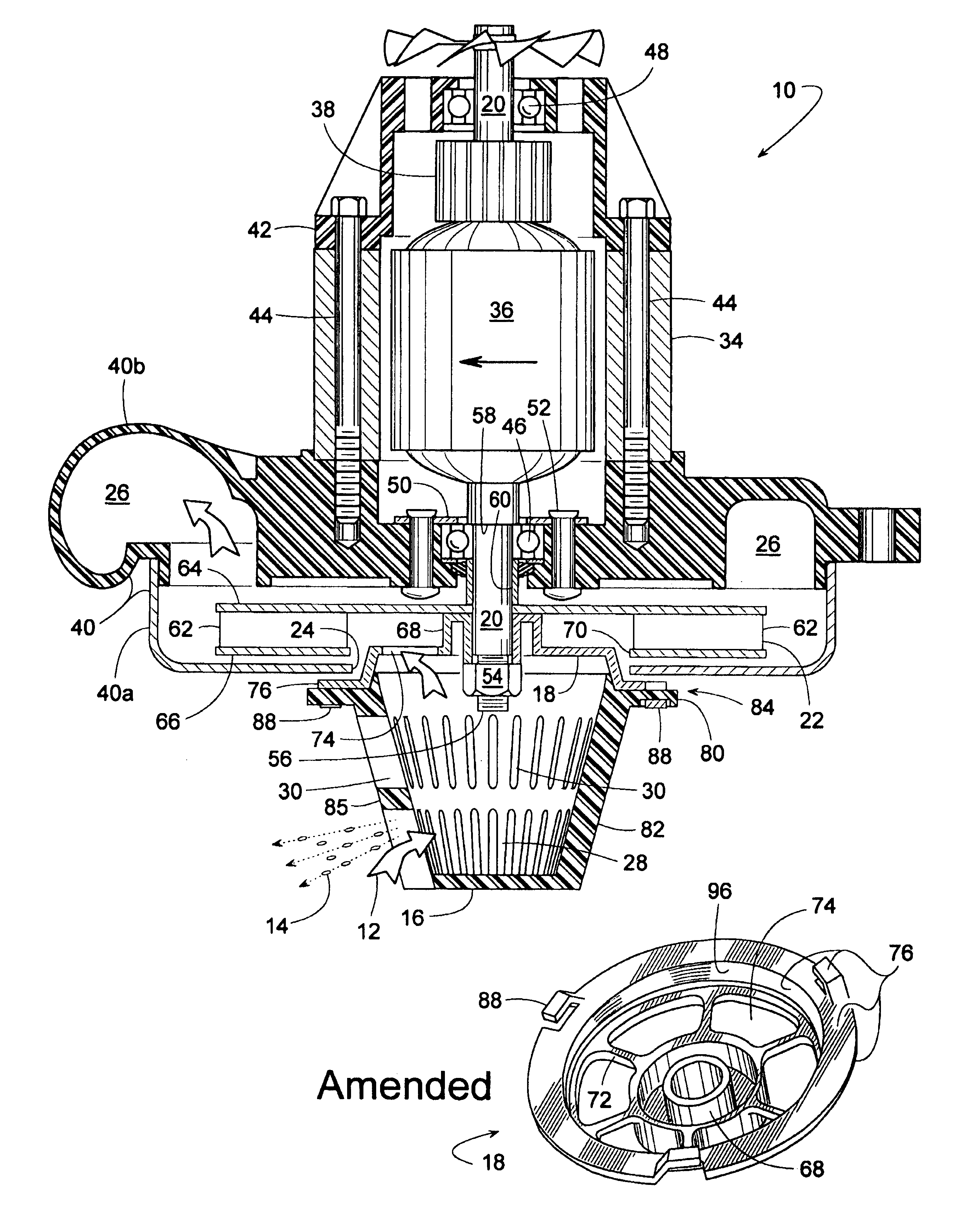
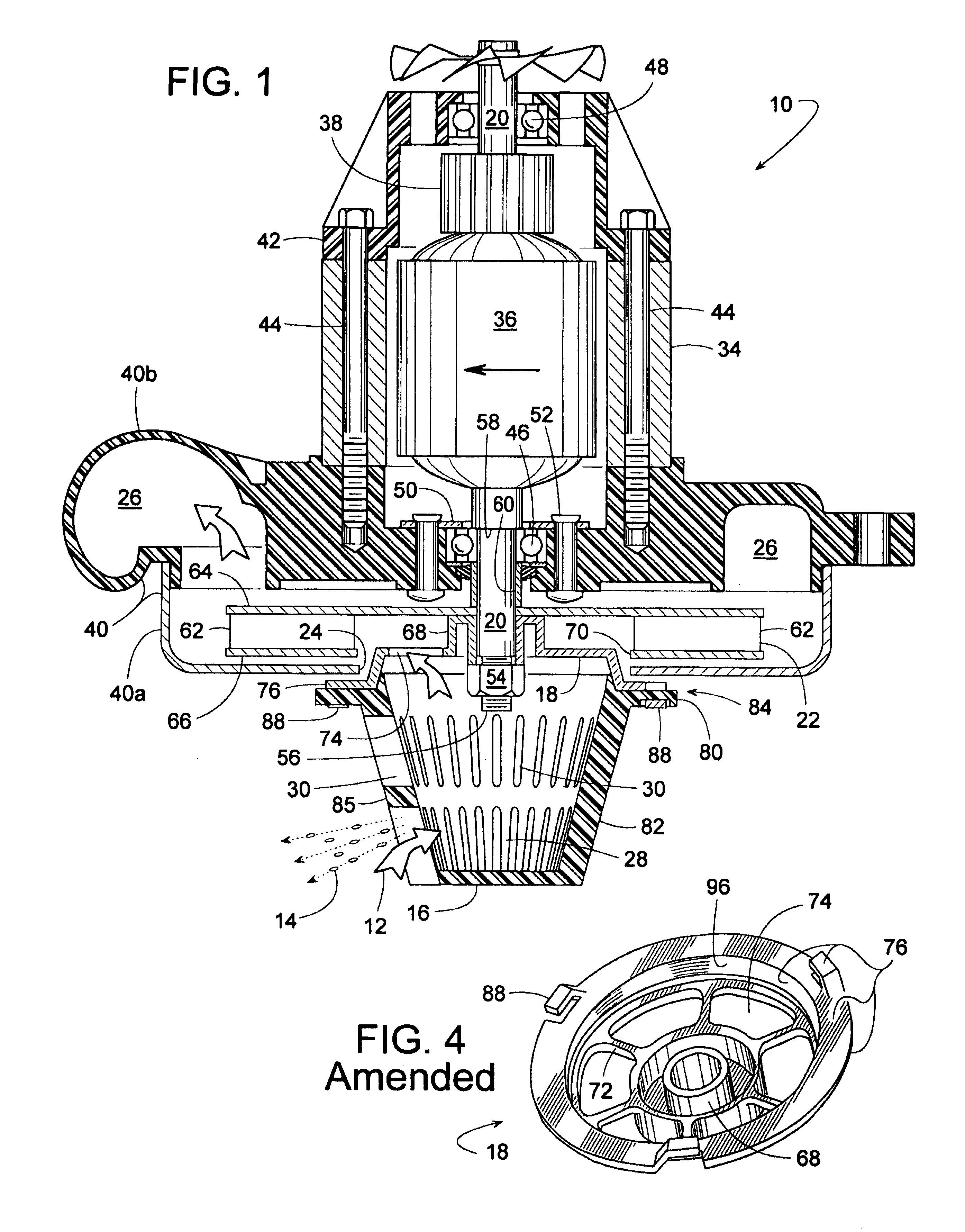
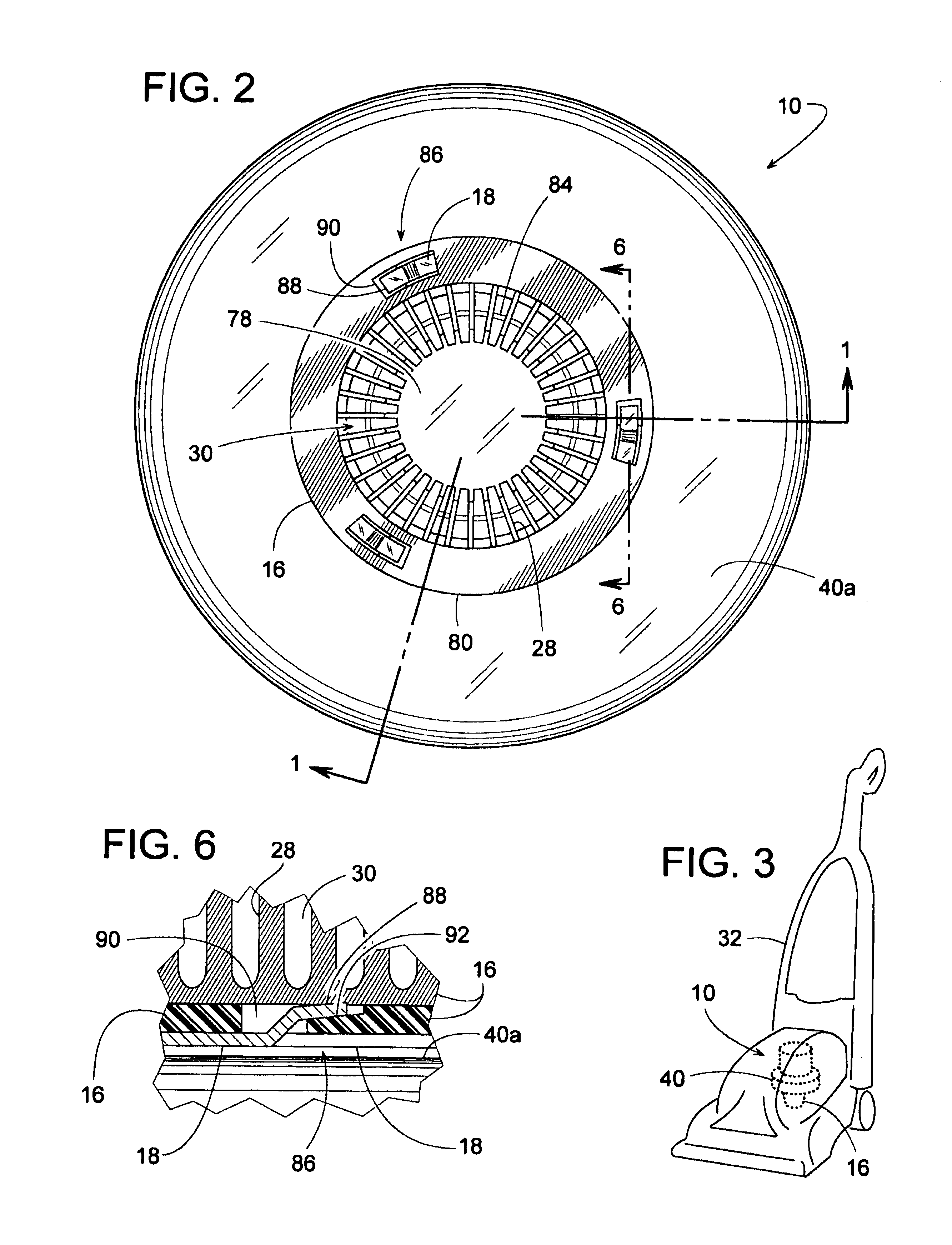
[0029]Referring to FIGS. 1 and 2, a motor-driven blower 10 for moving air 12 and separating moisture or water droplets 14 therefrom includes a rotating separator cup 16 attached to a spider bracket 18. Bracket 18 is attached to the blower's rotor shaft 20 so that as shaft 20 rotates an impeller 22 for forcing air 12 from an inlet opening 24 to discharge outlet 26, shaft 20 also rotates spider brackets 18 and separator cup 16. Fins 20 on separator cup 16 centrifugally sling water droplets 14 outward away from inlet 24 while allowing air 12, which is lighter than the droplets, to enter inlet 24 by passing through a plurality of separator openings 30 between the fins. In a currently preferred embodiment, blower 10 can be for a vacuum appliance 32 (FIG. 3) such as a wet / dry shop vac, wet carpet cleaner, water filtration unit, water extractor unit, etc. Additional information about separator cup 16 and spider bracket 18 will be explained after a brief description of other components of b...


PUM

PropertyMeasurementUnit
shallow angleaaaaaaaaaa
perimeteraaaaaaaaaa

Abstract

A motor-driven blower, particularly suited for carpet cleaners and other wet vacuuming appliances, includes a rotating separator cup to impede water droplets and foam from being drawn into the blower. The separator cup is removably connected to a spider bracket that is mounted more permanently to one end of the motor shaft. Since the separator cup is not directly connected to the motor shaft, the cup can be removed without disturbing the rest of the blower. Thus, the blower can be run either with or without the separator cup. Moreover, by not attaching the separator cup directly to the motor shaft, the shaft can be made shorter to minimize vibration and noise at high rpm's.

Description

BACKGROUND OF THE INVENTION[0001]1. Field of the Invention[0002]The subject invention generally pertains to motors for vacuum equipment and more specifically to a gas / liquid separator for such a motor.[0003]2. Description of Related Art[0004]Motor-driven fans for creating a vacuum in equipment known as wet / dry shop vacs, wet carpet cleaners, water filtration units, water extractor units, etc., are exposed to a significant amount of moisture-laden air or foam. To reduce the amount of moisture drawn into the fan and / or motor, a rotating separator can be attached to the end of the motor shaft at the fan's inlet. A typical separator includes a series of peripheral fins that centrifugally sling water droplets outward away from the fan's inlet while allowing the air, which is lighter than the droplets, to enter the fan by passing between the fins.[0005]Examples of such separators are disclosed in U.S. Pat. Nos. 6,391,101; 6,174,350; 6,162,287; 5,902,386; 5,096,475; 5,090,974; 5,030,257; 2...

Claims


Application Information

Patent Timeline
Patent Type & Authority Patents(United States)
IPC IPC(8): B01D45/14
CPCA47L5/22A47L7/0004A47L9/188B01D45/14
Inventor LAVASSER, LEONARD J.MANCL, DENNIS J.
Owner LAVASSER LEONARD J
Why Eureka
Try Eureka