Variable temperature seat

a seat and variable temperature technology, applied in the field of variable temperature seats, can solve the problems of seat occupants' back and other pressure points sweating, vehicle seats being very hot and uncomfortable for a long time, and achieving the effect of optimal operation without, reducing the number of parts and complexity, and reducing the cos

Inactive Publication Date: 2010-09-28
GENTHERM INC
View PDF49 Cites 84 Cited by
  • Summary
  • Abstract
  • Description
  • Claims
  • Application Information

AI Technical Summary

Benefits of technology

[0017]In yet another alternate embodiment, the seams that are already present in the seat can be utilized as either primary or secondary channels to direct air flow next to the occupant. The sewn seams can be utilized as distribution channels, to supplement or replace the reticulated foam layer. Air distribution is accomplished through the seat's sewn seams to direct air to the occupant from the channels or subchannels. The seams have the advantage of eliminating any barriers of fabric and allowing the air to flow so that it will be in direct contact with the occupant.
[0018]The invention is easily integratable into existing seat construction methods. In a preferred embodiment, the invention requires substantially the same number of parts as existing automotive seats. Using less parts and complexity than previous air distribution techniques results in a lower cost to utilize this invention. Further, the mechanical comfort of the seat is not appreciably affected, as generally the same basic types of materials that are used in vehicle seats today are utilized for the air distribution method and apparatus. The seat styling and design are also not appreciably changed. Finally, the inherent tendencies of the existing foam construction of vehicle seats is a good insulator for holding and maintaining the conditioned air until it is delivered to the seat occupant. This achieves maximum comfort levels, that this invention provides in a very energy efficient mode, while requiring no complex systems or devices in order to practice this invention.

Problems solved by technology

For example, an automotive vehicle exposed to the summer weather, where the vehicle has been parked in an unshaded area for a long period of time, can cause the vehicle seat to be very hot and uncomfortable for the occupant for some time after entering and using the vehicle, even with normal air conditioning.
Even with normal air-conditioning, on a hot day, the seat occupant's back and other pressure points may remain sweaty while seated.
One limitation of this embodiment is that it does not use common elements presently available that can be used to construct vehicle seats.
While this embodiment provides some heating and cooling, it nevertheless does not achieve optimal operation without sacrifice of the comfort of the user.
Also, excessive accumulation of condensate can occur, with the potential of spilling and damaging the vehicle in the vicinity of the seat.
However, the same problems of non standard and specialized parts remains.
If the condensate collection system were not provided, then undue liquid accumulation would occur within the main exchanger housing for conditioned air.
This is undesirable because excessive condensate accumulation reduces the main exchanger performance.
Further problems with the techniques available are that the air conditioning supply units and their accompanying condensate collection systems may require additional wiring apparatus.
Other problems that have been experienced with existing techniques include that the construction of the seats are not easily integratable into existing seat construction methods.
The techniques require a significantly greater number of parts as compared to existing automotive seats, and often require non-standard parts.
The parts used are typically more complex than other existing air distribution methods.
In the past, this has lead to increased costs if individualized occupant cooling was provided.
Also, the mechanical comfort of the seat is appreciably affected in the techniques employed, as compared to the comfort provided by standard automotive seats, wherein the user is able to distinguish between the comfort of the two.
Further, the current techniques are problematic in the ability for vehicle designers to provide modern seating embodiments and stylistic designs.
Yet another problem is that the techniques employed above do not provide good insulation for holding conditioned air until it is used by the occupant.

Method used


Image

  • Variable temperature seat
  • Variable temperature seat
  • Variable temperature seat

Examples


Embodiment Construction

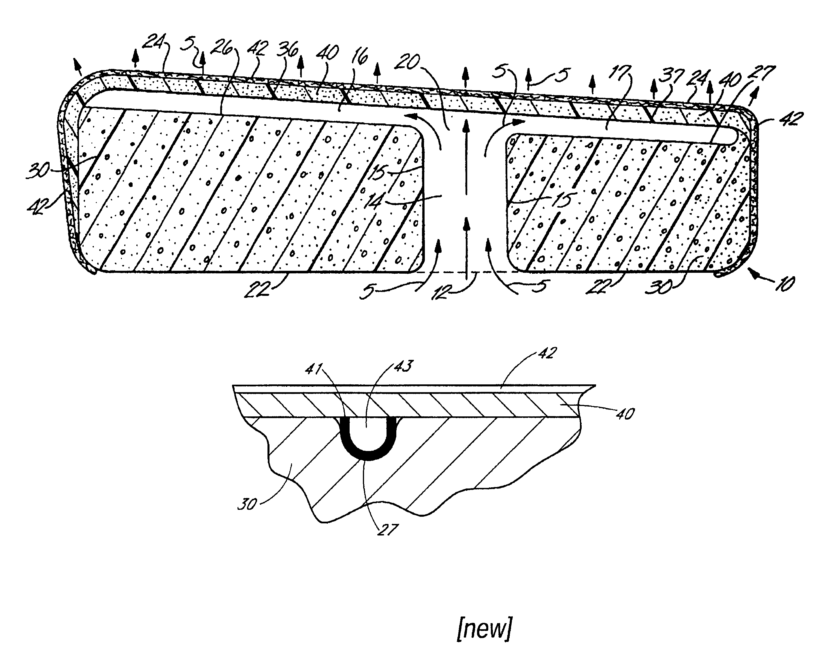
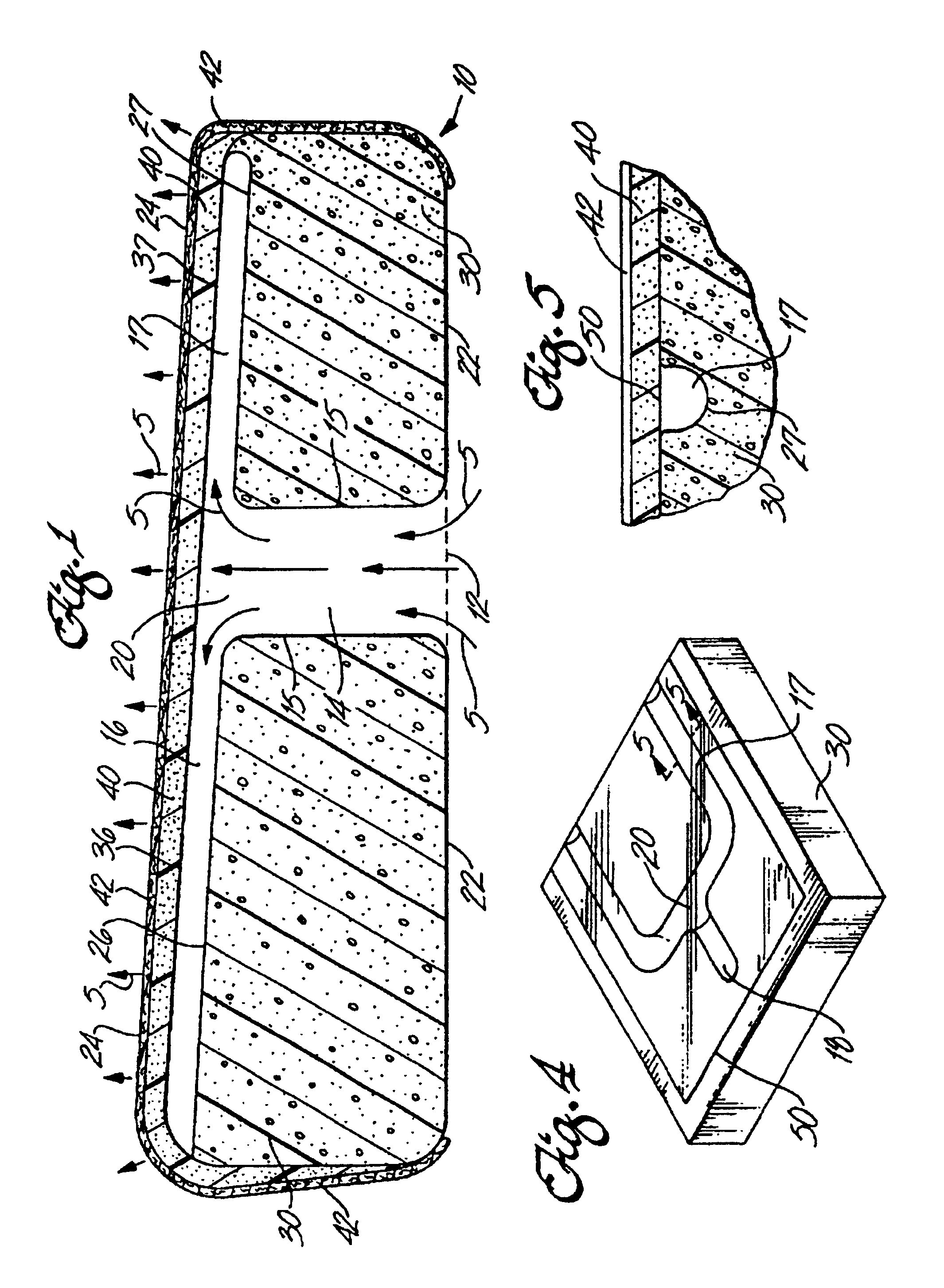
[0032]In a first embodiment of the invention, conditioned air 5, represented by arrows, is supplied to the air inlet 12 of an automotive seat cushion 10 as shown in FIG. 1. The conditioned air 5 passes through the main channel 14 and is divided via the manifold 20 into subchannels 16, 17, as shown in FIG. 1. The air inlet 12 is located on the entrance side 22, and is opposite the occupant side 24 of the seat cushion 10. The air inlet 12, the channel walls 15, and a portion of the subchannel walls 26, 27 are substantially formed by standard automotive seat cushion foam material 30. The subchannel walls 36, 37 nearest the occupant side 24 of the seat cushion 10 preferably are formed by reticulated foam 40. The reticulated foam is encapsulated by a layer of automotive upholstery 42 that is preferably air permeable.

[0033]The conditioned air 5 passes from the subchannel regions into the reticulated foam layer 40. Within the reticulated foam, the conditioned air is free to move both verti...


PUM


Abstract

A seating construction with a plurality of plenums into which is received temperature conditioned air. The air passes through the seat via a plurality of channels formed in the foam of the seat cushion. The air then migrates through a reticulated foam layer that is itself covered with an air permeable layer of material. The reticulated foam and stitching of the seat fabric facilitate diffusion of the air from the foam channel conduits. The air then convectively circulates against and near the occupant of the seat to facilitate climate control around the occupant.

Description

[0001]Related Applications: The present application is a continuation of prior application Ser. No. 09 / 239,054, filed Jan. 27, 1999.BACKGROUND OF THE INVENTION[0002]1. Field of the Invention[0003]The invention provides a method and apparatus for climate control of an individualized occupant seat In the practice of this invention, there is a method and apparatus for providing conditioned air to a vehicle seat's occupant. Conditioned air is obtained from a central source in the vehicle and is channeled through the seat. The air is then separated into a plurality of smaller subchannels via a manifold. The air is then further divided up, i.e., diffused, through a layer of reticulated foam. This reticulated foam takes the place of the upholstery backing foam that is normally used in a vehicle seat. The air passes through the foam, both perpendicular to, as well as parallel with, the seat cushion surface. The air, in exiting the reticulated foam, is directed through the seat covering. The...

Claims


Application Information

Patent Timeline
Patent Type & Authority Patents(United States)
IPC IPC(8): A47C7/74B60N2/90
CPCA47C7/74B60N2/449B60N2/5657B60N2/5628B60N2/986
Inventor GREGORY, CHRISTIAN T.NOLES, DAVID R.GALLUP, DAVID F.HELLER, DAVID H.
Owner GENTHERM INC
Why Eureka
Try Eureka