Leak check for fuel vapor purge system

a technology of leak detection and purge system, which is applied in the direction of combustion air/fuel air treatment, machines/engines, mechanical equipment, etc., can solve the problems of fuel vapor purge system variable new problems, error in leak detection, and rapid change of fuel tank pressure, so as to reduce power consumption

Inactive Publication Date: 2010-10-19
FCI AMERICAS TECH LLC
View PDF21 Cites 4 Cited by
  • Summary
  • Abstract
  • Description
  • Claims
  • Application Information

AI Technical Summary

Benefits of technology

[0011]It is one object of the invention to promote reliability of leak check in a fuel vapor purge system.
[0025]Further, when the pressure detected by the pressure detecting means is equal to or smaller than a predetermined determinant, the first valve may be prevented from being opened. In the case in which the pressure of the fuel vapor purge system has already been decreased to the determinant or lower, for example, a vicinity of the atmospheric pressure when the leak check has been finished, it is not necessary to open the first valve. Thereby, when the leak check has been finished, wasteful drive to open and close the first valve can be avoided and power consumption can be reduced while the engine is being stopped to operate.

Problems solved by technology

Various new problems are posed in the fuel vapor purge system which can hermetically be closed.
For example, under a state in which the system is hermetically closed, rapid deformation of the fuel tank brings about rapid change in pressure in the fuel tank.
Therefore, there is a concern of causing an error in the leak check.
Particularly, a fuel tank made of resin is more liable to deform than a fuel tank made of a metal plate.
Such an excessive pressure exposes a component of the fuel vapor purge system to a severe pressure difference over a long period of time to thereby bring about deformation or deterioration in function.
For example, an excessive pressure difference is operated to a fuel tank over a long period of time.
In other aspect, negative pressure hampers the leak of the fuel vapor from the fuel vapor purge system to the atmosphere.

Method used


Image

  • Leak check for fuel vapor purge system
  • Leak check for fuel vapor purge system
  • Leak check for fuel vapor purge system

Examples


first embodiment

[0048](First Embodiment)

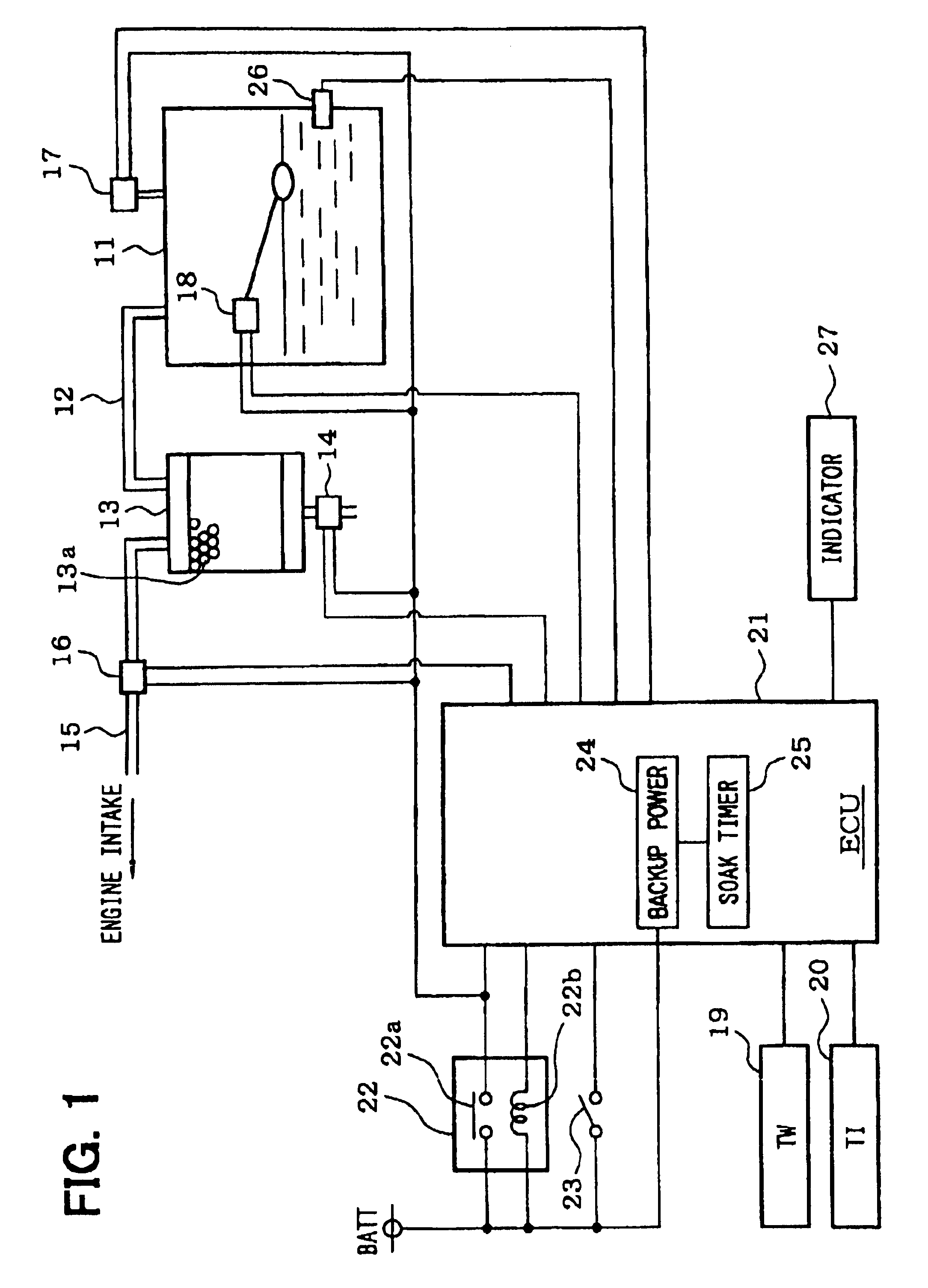
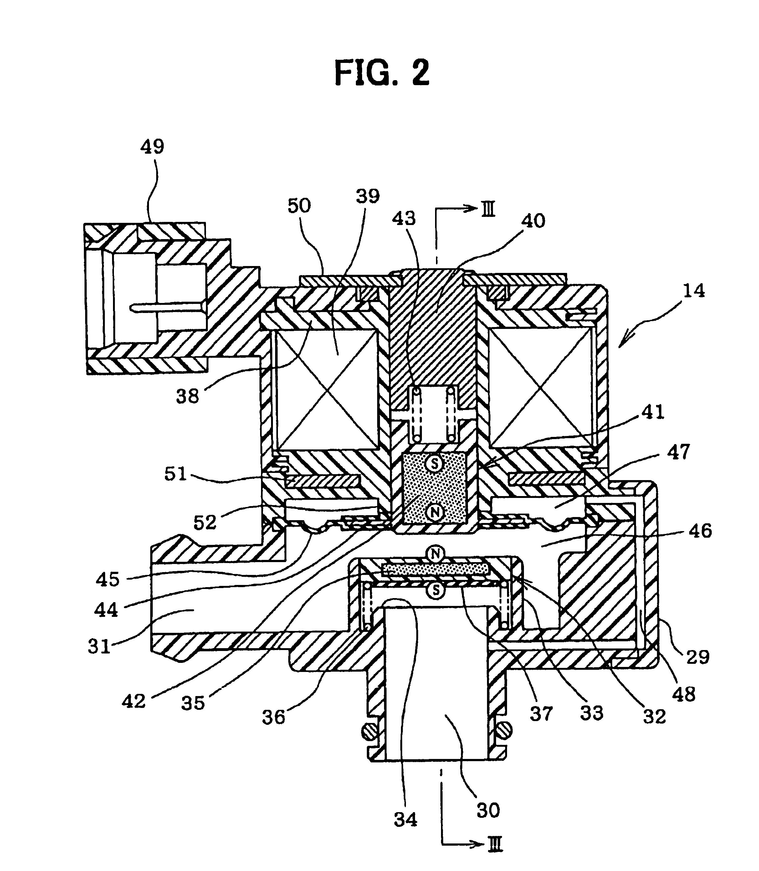
[0049]An explanation will be given of a first embodiment of the invention in reference to FIG. 1 through FIG. 7 as follows. First, an explanation will be given of a constitution of a fuel vapor purge system in reference to FIG. 1. A fuel tank 11 is molded by resin. The fuel tank 11 is connected with a canister 13 via a fuel vapor path 12. An adsorber 13a of active carbon or the like for adsorbing the fuel vapor is contained in the canister 13. Further, an atmosphere communicating path of a bottom face portion of the canister 13 is attached with a canister valve 14 (CCV) of a power saving type, mentioned later.

[0050]Meanwhile, between the canister 13 and an engine intake system, there is provided a purge path 15 for purging (discharging) fuel vapor adsorbed to the adsorber in the canister 13 to the engine intake system and a purge valve 16 for controlling a purge flow rate is provided at a middle of the purge path 15. The purge valve 16 is constituted by a nor...

second embodiment

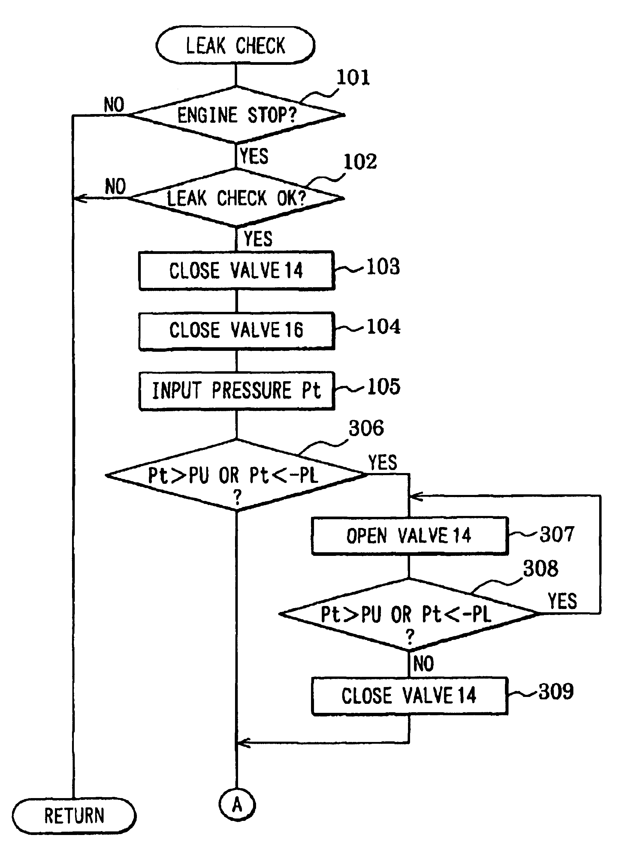
[0090](Second Embodiment)

[0091]Next, an explanation will be given of a second embodiment of the invention in reference to FIG. 8 to FIG. 12. Elements the same as or similar to those in the first embodiment are attached with the same notations and an explanation thereof will not be repeated. According to the second embodiment, by executing a leak check routine shown in FIG. 8 and FIG. 9, during leak check after stopping the engine (after making IG switch 23 OFF) the pressure Pt is restricted by a predetermined positive pressure side restricted value PU and predetermined negative pressure side restricted value −PL and when the pressure Pt is rapidly changed (when deformation of fuel tank is brought about) in leak check, leak check is cancelled and the positive side restricted value PU or the negative pressure restricted value −PL is corrected in a direction of approaching the atmospheric pressure.

[0092]At step 306, it is determined whether the pressure Pt is higher than the predetermi...

third embodiment

[0114](Third Embodiment)

[0115]An explanation will be given of a third embodiment in reference to FIG. 14 through FIG. 16 as follows. A fuel vapor purge system according to the third embodiment is provided with components the same as those of the first embodiment. Leak check processings of the third embodiment differ from those of the first embodiment. According to the third embodiment, there is added a processing of temporary opening the canister valve 14 after finishing to check the leak. In the following explanation, elements the same as or similar to those of the first embodiment are added with the same notations and an explanation thereof will not be repeated.

[0116]Meanwhile, according to a conventional general fuel vapor purge system, there is used an electromagnetic valve of a normally open type for the canister valve in order to communicate the canister to the atmosphere in stopping to operate the engine and therefore, even after stopping to operate the engine, until finishin...


PUM


Abstract

A leak check system executes a leak check processing. In the leak check processing, the system closes a canister valve and a purge valve to close the fuel vapor purge system. Then, the system detects and monitors a pressure in the fuel vapor purge system. During the leak check processing, the system detects a rapid change of the pressure that is caused by a deformation of a wall of a fuel tank. The system cancels or suspends the processing to avoid erroneous detection of the leak. If the leak check is canceled, the system opens the canister valve to open the fuel vapor purge system.

Description

CROSS REFERENCE TO RELATED APPLICATION[0001]This application is based on Japanese Patent Applications No. 2001-274767 filed on Sep. 11, 2001 and No. 2001-274768 filed on Sep. 11, 2001 the contents of which are incorporated herein by reference.BACKGROUND OF THE INVENTION[0002]1. Field of the Invention[0003]The present invention relates to a fuel vapor purge system, and more particularly, an apparatus and method of detecting a leak in the fuel vapor purge system.[0004]2. Related Art[0005]According to a conventional fuel vapor purge system, fuel vapor generated from a fuel tank is stored in an active carbon canister. The fuel vapor stored in the active carbon canister is purged to an intake path of an engine and combusted by the engine when a predetermined condition is satisfied. A purge valve is provided between the active carbon canister and the intake path to thereby control an amount of the fuel vapor to be purged. The path is provided with a canister valve.[0006]It is requested fo...

Claims


Application Information

Patent Timeline
Patent Type & Authority Patents(United States)
IPC IPC(8): F02M33/02F02M25/08
CPCF02M25/0809F02M25/0836F02M2025/0845
Inventor MIWA, MAKOTOMORINAGA, SYUJIROMAEGAWA, YOSHINORIWAKAHARA, KEIJI
Owner FCI AMERICAS TECH LLC
Why Eureka
Try Eureka