
Profile grinding machine

a profile grinding machine and profile technology, applied in the direction of grinding machines, automatic grinding control, metal-working equipment, etc., can solve the problems of elongated total time period required for grinding operations, inability to perform grinding operations, and complicated profile grinding operations

Active Publication Date: 2014-08-12
MITSUI HIGH TEC INC
View PDF19 Cites 0 Cited by
  • Summary
  • Abstract
  • Description
  • Claims
  • Application Information

AI Technical Summary

Benefits of technology

The invention is about a profile grinding machine that can smoothly grind a recess in the side of a workpiece. The machine has three moving devices that allow the workpiece to be moved in both the X and Y directions, which changes the depth of the cut made by the grinding stone. This allows for precise shaping of the recess's inner faces. Additionally, the machine has a mechanism that prevents the grinding stone from interfering with the workpiece during its rotation. The grinding stone can be easily aligned with the machine's rotation axis, regardless of any wear or changes in its size. This improves the machine's efficiency and flexibility.

Problems solved by technology

In case the angles of inclination of the ground faces to be formed are different for the individual faces, therefore, the angles of the grinding stone have to be readjusted for the individual faces thereby to complicate the profile grinding operations.
As a result, when the leading end portion 86 of the grinding stone 85 approaches the other side of the recess 82, there arise a problem that the side portion of the grinding stone 85 interferes with the other side of the recess 82 so that the grinding operation cannot be performed.
As a result, there arises a problem that the grinding stone 85 collides against the other side of the recess 82, as shown in FIG. 8C.
As a result, the preparing steps before the grinding operations increase to raise a problem that the total time period required for the grinding operations is elongated.

Method used


Image

  • Profile grinding machine
  • Profile grinding machine
  • Profile grinding machine

Examples


Embodiment Construction

[0028]Subsequently, the invention is described on its mode of embodiment with reference to the accompanying drawings so that it may be understood.

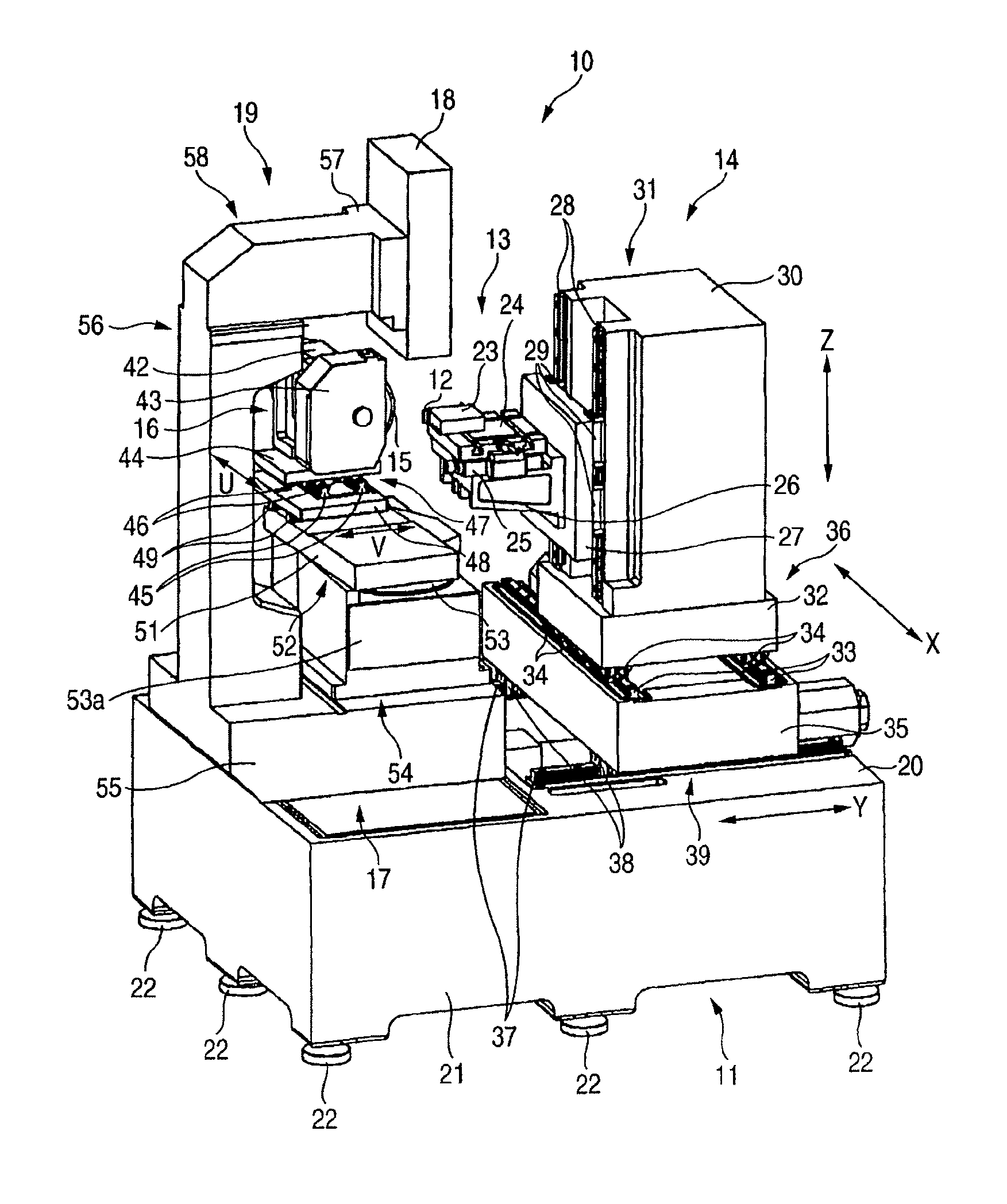
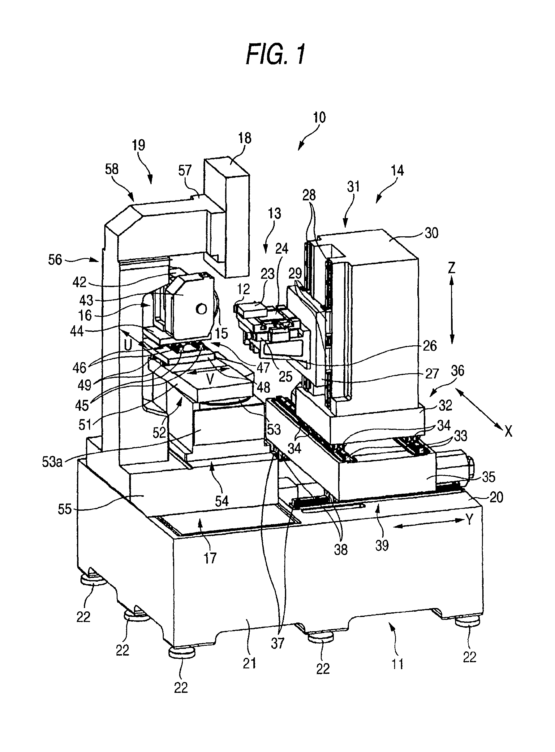
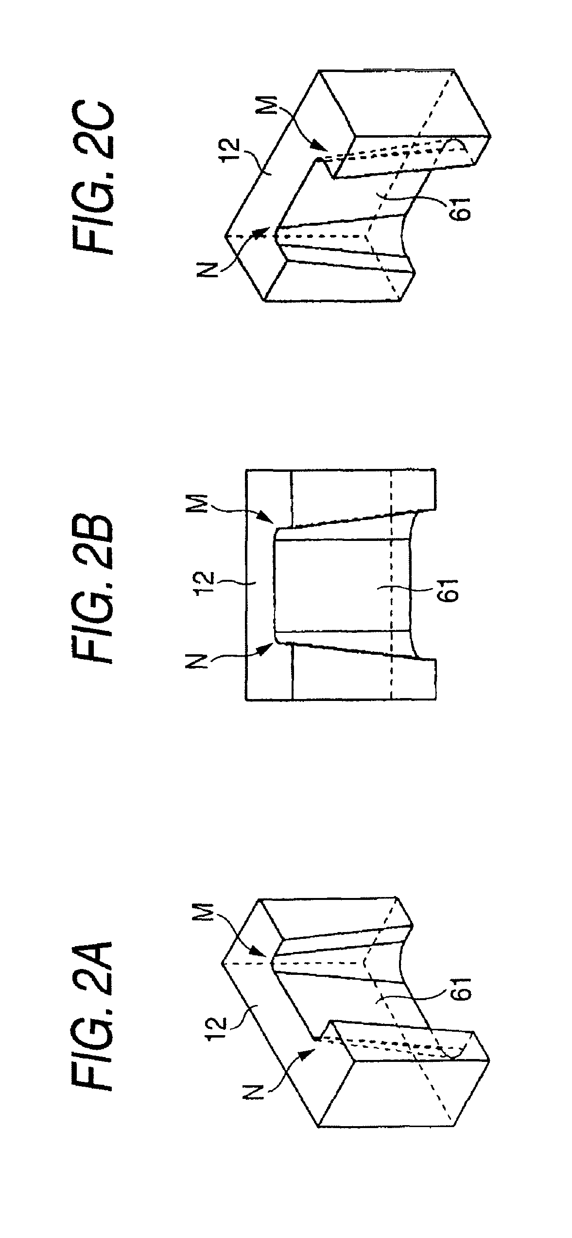
[0029]Here, FIG. 1 is a perspective view of a profile grinding machine according to one mode of embodiment of the invention; FIGS. 2A to 2C are perspective view of a work to be ground by the profile grinding machine; FIG. 3 is a perspective view of a turning mechanism, which is disposed in a grinding stone unit of the same profile grinding machine; FIG. 4 is a perspective view of an image pickup mechanism of the same profile grinding machine; FIG. 5 is a perspective view showing the situation, in which the work is ground on its face inclined in a vertical direction by the same profile grinding machine; and FIG. 6 is a top plan view showing the situation, in which the work is ground on its face inclined in a vertical direction by the same profile grinding machine.

[0030]As shown in FIG. 1, a profile grinding machine 10 includes: a base 11 in...


PUM


Abstract

The profile grinding machine includes: a base; a work unit disposed on one side on the base and including a work table for gripping a work; and a stone unit disposed on the other side on the base and including a stone rotating mechanism for holding and rotating a grinding stone on its axis. The work unit includes first to third moving device for supporting and moving the work table in an X-direction and a Y-direction perpendicular to each other in a horizontal plane, and in a Z-direction normal to the horizontal plane, respectively. The stone unit includes turning mechanism for turning the grinding stone about a vertical axis substantially coinciding with the leading end portion of the grinding stone.

Description

BACKGROUND OF THE INVENTION[0001]1. Field of the Invention[0002]The present invention relates to a profile grinding machine for grinding a recess made open in the side face of a work, smoothly.[0003]2. Related Art[0004]Conventionally, in case a ground face inclined with respect to a vertical line is formed in the inner face of a recess made open in the side face of a work, as shown in FIG. 2, the work is fixed on a work table, and the grinding stone is manually inclined before the grinding operation in accordance with the angle of inclination of the ground face to be formed, so that the moving direction of the leading end of the grinding stone is set in parallel with the ground face to be formed. In case the angles of inclination of the ground faces to be formed are different for the individual faces, therefore, the angles of the grinding stone have to be readjusted for the individual faces thereby to complicate the profile grinding operations. Thus, there has been proposed (as refe...

Claims


Application Information

Patent Timeline
Patent Type & Authority Patents(United States)
IPC IPC(8): B24B49/12
CPCB24B17/06B24B19/02
Inventor HIROSE, TADAOIWAKIRI, HIROSHIHIGUCHI, AKIKAZUNAGATA, ATSUSHI
Owner MITSUI HIGH TEC INC
Learn More