High field magnetic resonance

a high-field magnetic resonance and high-field technology, applied in the field of magnetic resonance, can solve the problems of low-field magnetic resonance not producing adequate signal-to-noise ratio, imaging speed and other performance,

Active Publication Date: 2018-09-04
RGT UNIV OF MINNESOTA
View PDF22 Cites 13 Cited by
  • Summary
  • Abstract
  • Description
  • Claims
  • Application Information

AI Technical Summary

Benefits of technology

The present invention is a system and method for magnetic resonance imaging (MRI) that allows for independent control of each channel's frequency, phase, time, space, and magnitude. The system includes a transceiver with a multichannel receiver and a multichannel transmitter, a magnetic resonance coil with multiple current elements, and a processor to control the current in each element. The processor can perform dynamic RF field control and non-linear algorithms to shim the coil. The system also includes a user input console to receive user selection for RF field optimization and can be used with a coil of at least 3 T. The technical effects of the invention include improved spatial and temporal resolution, improved signal-to-noise ratio, improved field shimming, and improved user experience.

Problems solved by technology

Magnetic resonance using low fields does not produce adequate signal to noise ratio, imaging speed and other performance.

Method used


Image

  • High field magnetic resonance
  • High field magnetic resonance
  • High field magnetic resonance

Examples


Embodiment Construction

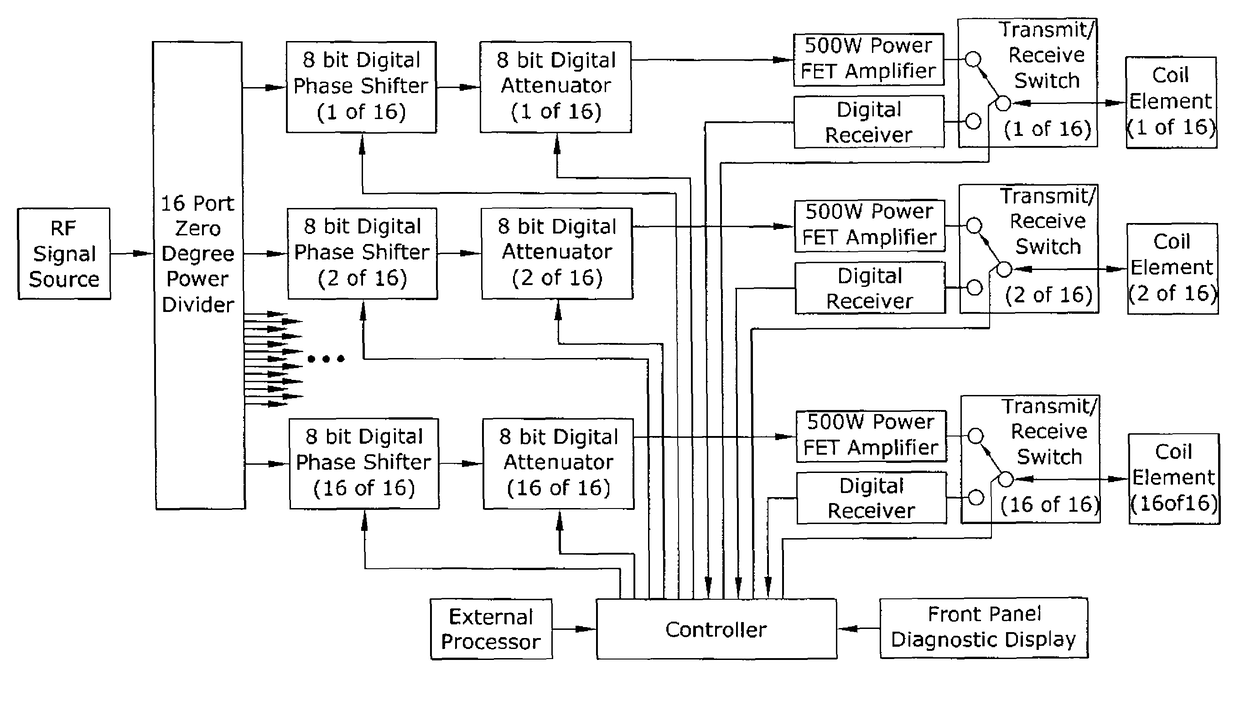
[0146]The following detailed description includes references to the accompanying drawings, which form a part of the detailed description. The drawings show, by way of illustration, specific embodiments in which the invention may be practiced. These embodiments, which are also referred to herein as “examples,” are described in enough detail to enable those skilled in the art to practice the invention. The embodiments may be combined, other embodiments may be utilized, or structural, logical and electrical changes may be made without departing from the scope of the present invention. The following detailed description is, therefore, not to be taken in a limiting sense, and the scope of the present invention is defined by the appended claims and their equivalents.

[0147]In this document, the terms “a” or “an” are used, as is common in patent documents, to include one or more than one. In this document, the term “or” is used to refer to a nonexclusive or, such that “A or B” includes “A b...


PUM


Abstract

A magnetic resonance system is disclosed. The system includes a transceiver having a multichannel receiver and a multichannel transmitter, where each channel of the transmitter is configured for independent selection of frequency, phase, time, space, and magnitude, and each channel of the receiver is configured for independent selection of space, time, frequency, phase and gain. The system also includes a magnetic resonance coil having a plurality of current elements, with each element coupled in one to one relation with a channel of the receiver and a channel of the transmitter. The system further includes a processor coupled to the transceiver, such that the processor is configured to execute instructions to control a current in each element and to perform a non-linear algorithm to shim the coil.

Description

CROSS-REFERENCE TO RELATED PATENT DOCUMENTS[0001]Notice: More than one reissue application has been filed for the reissue of U.S. Pat. No. 7,800,368. The reissue applications are U.S. patent application Ser. No. 13 / 623,637, which is the present application and a reissue application of U.S. Pat. No. 7,800,368; and U.S. patent application Ser. No. 14 / 060,105, which is a continuation reissue application of U.S. Pat. No. 7,800,368. This document claims the benefit of priority, under 35 U.S.C. Section 119(e), to J. Thomas Vaughan et. al, U.S. Provisional Patent Application Ser. No. 60 / 774,297, entitled MULTICHANNEL MAGNETIC RESONANCE IMAGING AT HIGH FIELDS, filed on Feb. 17, 2006, all of which is hereby incorporated by reference.[0002]The invention described herein was made with government support under Grant Numbers EB000895, R01 EB000895, R01 EB000895-04, P41 RR08079, P41 RR0807954, BTRR P41 008079, RR008079, RR08079, S10 RR139850, R33 CA94318, R01 CA94200, R42 RR13230, PAR 02-010, RO1...

Claims


Application Information

Patent Timeline
Patent Type & Authority Patents(United States)
IPC IPC(8): G01V3/00G01R33/48G01R33/32G01R33/58G01R33/24G01R33/561G01R33/341
CPCG01R33/341G01R33/246G01R33/583G01R33/5612G01R33/5659G01R33/546G01R33/543G01R33/343
Inventor VAUGHAN, J THOMASVAN DE MOORTELE, PIERRE-FRANCOISDELABARRE, LANCEOLSON, CHRIS EORSER, HEATHERGOPINATH, ANANDUGURBIL, KAMILSNYDER, CARLADRIANY, GREGORAKGUN, CANTIAN, JINFENGSTRUPP, JOHNANDERSEN, PETER M
Owner RGT UNIV OF MINNESOTA
Why Eureka
Try Eureka