Non-Positive-Displacement Machine Comprising a Spiral Channel Provided in the Housing Middle Part

a technology of spiral channel and housing middle part, which is applied in the direction of positive displacement liquid engine, liquid fuel engine, piston pump, etc., can solve the problem of only having a high technical manufacturing complexity, and achieve the effect of reducing space requirements, reducing the length of the turbine shaft and the overall housing length

Inactive Publication Date: 2008-02-14
MANN HUMMEL GMBH
View PDF3 Cites 4 Cited by
  • Summary
  • Abstract
  • Description
  • Claims
  • Application Information

AI Technical Summary

Benefits of technology

[0005]The arrangement of the fluid flow engine according to the invention is based on the shifting of at least one part of the spiral geometry to a central housing part. This therefore forms at least part of a turbine housing or a compressor housing. The spiral geometry is sealed on the outside by a cover, with the cover forming the second part of the spiral geometry. Therefore, a cross section of the spiral channel is defined by the central housing part and the cover. A parting plane aligned perpendicular to a turbine shaft mounted in the central part of the housing is situated between the cover and the central part of the housing.
[0006]The fluid flow engine may be, for example, a turbo engine, e.g., an exhaust gas turbocharger or a secondary air charger for secondary air injection into a catalytic converter. However, it may also be used as a simple turbine for converting a mass flow into a rotor movement.
[0007]The inventive fluid flow engine advantageously makes it possible to shift a spiral contour into the central housing part, so the flow cross section of the spiral contour can be manufactured by the compression molding method without any undercuts. In addition, the narrower design of the cover results in reduced space requirements.
[0008]According to one embodiment of the invention, the cover on the area adjacent to the spiral contour is constructed to be flat. The spiral contour is formed exclusively in the central housing part. The contour corresponding to the turbine rotor and the axial inlet and discharge connections may be implemented without any changes.
[0009]This embodiment advantageously makes it possible to meet the high demands of the spiral geometry with respect to geometry and dimensional tolerance. Due to the simple geometry of the cover, it may also be made of plastics such as polyamide [nylon].
[0010]In one variant, the spiral geometries on the turbine side and the compressor side are arranged in the central housing part. Therefore, the length of the turbine shaft and thus the total housing length can be shortened. This further reduces the required design space.

Problems solved by technology

This embodiment can be manufactured only with a high technical manufacturing complexity because of the shaping involved.

Method used


Image

  • Non-Positive-Displacement Machine Comprising a Spiral Channel Provided in the Housing Middle Part
  • Non-Positive-Displacement Machine Comprising a Spiral Channel Provided in the Housing Middle Part
  • Non-Positive-Displacement Machine Comprising a Spiral Channel Provided in the Housing Middle Part

Examples


Embodiment Construction

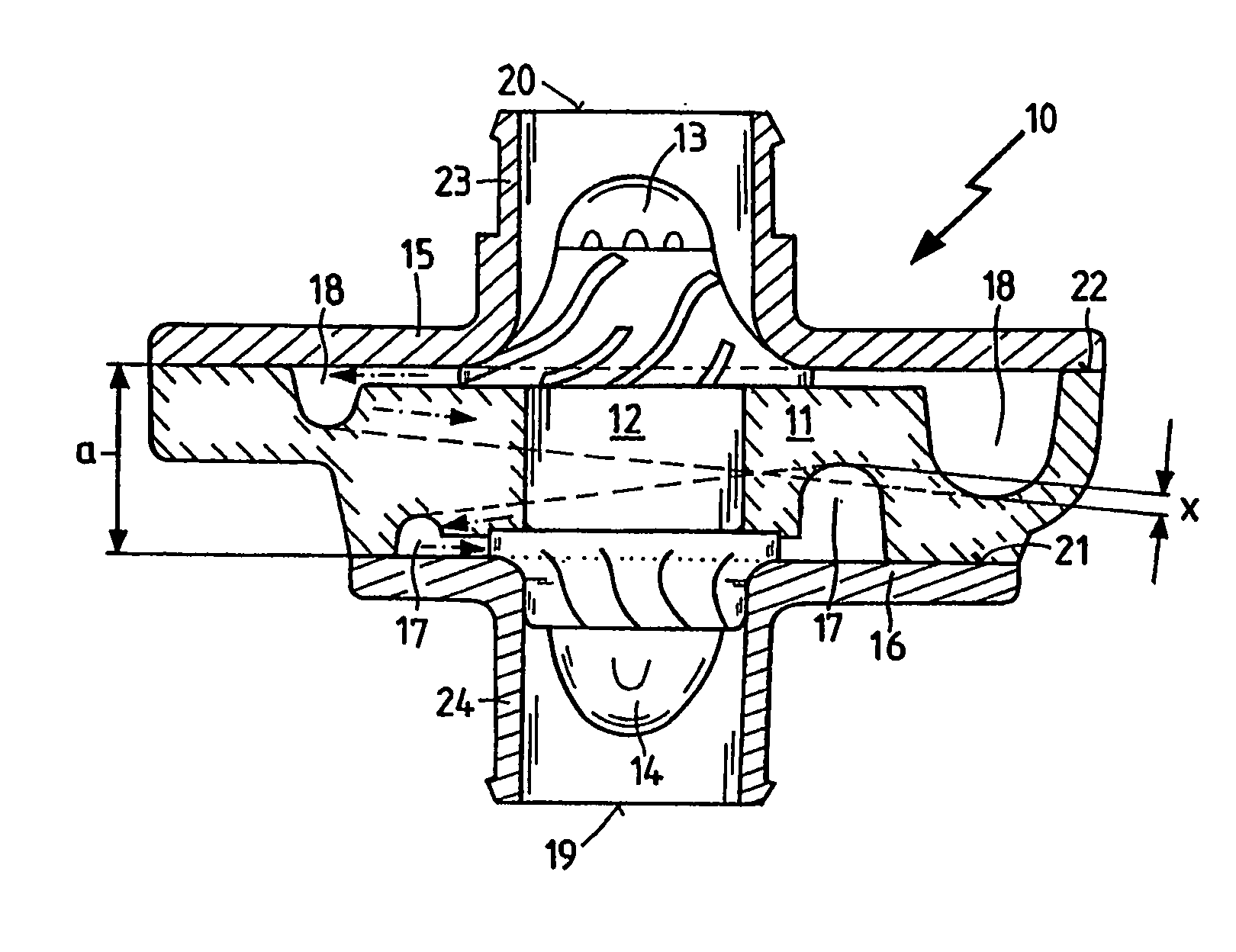
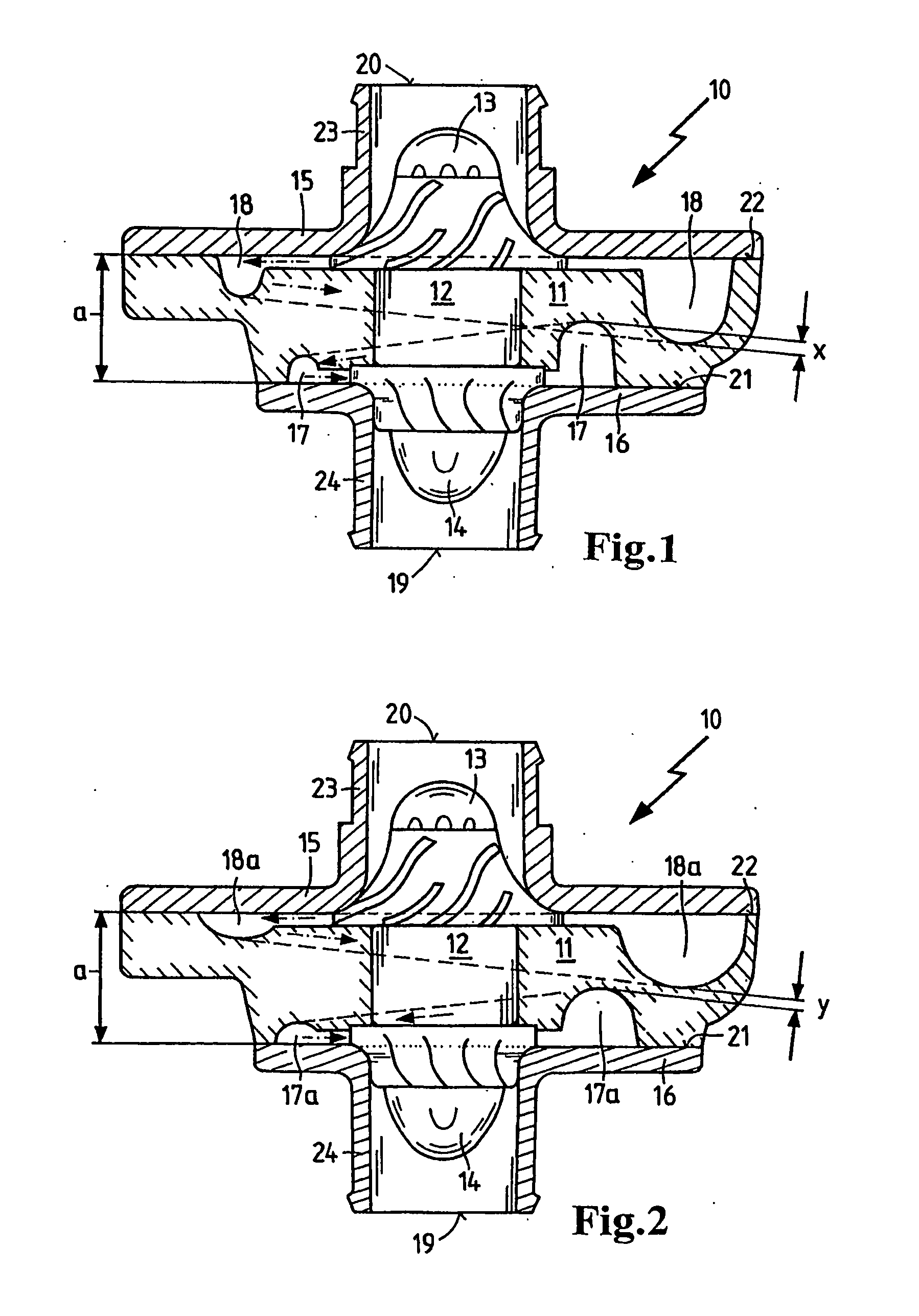
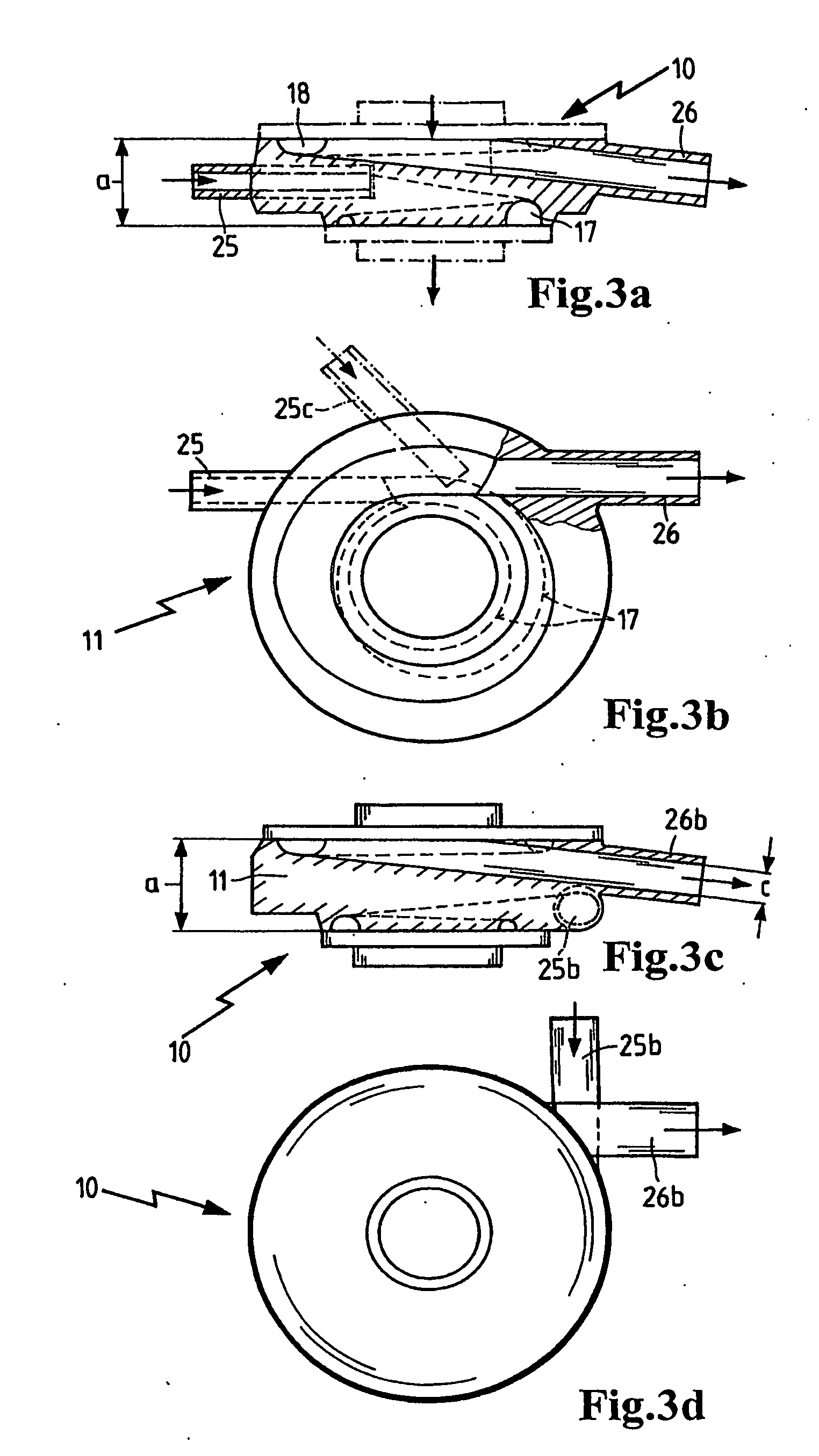
[0031]FIG. 1 shows an inventive fluid flow engine 10 in a full sectional view, with a turbine shaft 12 mounted in a central housing part 11. A compressor rotor 13 is rigidly mounted on the turbine shaft 12 and a turbine rotor 14 is rigidly mounted on the opposite side. The central housing part 11 is sealed on opposite ends by a turbine cover 16 and a compressor cover 15. These two covers 15, 16 are clamped on planar parting planes 21, 22 on the central housing part. Spiral channels 17, 18 are molded into both sides of the central housing part 11; these spiral channels are sealed by the covers 15, 16 on the planar parting planes 21, 22 on both cover ends. Between the parting planes 21, 22, the central housing part has a housing thickness a.

[0032]The spiral channels 17, 18 undergo a change in their circular cross-sectional area in the spiral contour, intersecting one another in the axial direction of the turbine shaft 12 with the dimension x in the area of the largest cross-sectional ...


PUM


Abstract

A non-positive-displacement machine (10), particularly a turbomachine for producing a mass flow, having a central housing part (11) inside which a turbine shaft is mounted. A turbine housing is mounted on the central housing part (11) on a turbine side and a compressor housing is mounted on the central housing part (11) on a compressor side. The spiral channels (17, 18) required for the compressor side and for the turbine side can be arranged in a partial area inside the covers (15, 16) and at least in one partial area inside the central housing part (11). This permits the contours, which are required for the spiral channels (17, 18) and which are geometrically complex, to be constructed in the central housing part (11).

Description

BACKGROUND OF THE INVENTION[0001]The invention relates to a fluid flow engine for producing a mass flow.[0002]German Patent DE 10297203 describes a turbine housing for an exhaust gas turbocharger in which a turbine rotor driven by exhaust gases drives a compressor rotor. The compressor rotor is connected by a rigid shaft to the turbine rotor. The shaft which carries the compressor wheel and the turbine wheel is mounted in a central housing part which is sealed on the turbine end by a turbine housing and on the compressor end by a compressor housing. The exhaust gas flows tangentially into a spiral tapering contour of the turbine housing and is directed in a targeted manner at turbine blades of the turbine rotor. The turbine rotor is driven by these turbine blades. The exhaust gas flows further axially out of the turbine housing and to the turbine wheel. On the compressor end a mass flow is conveyed axially from the compressor rotor through the spiral channels to the tangential outfl...

Claims


Application Information

Patent Timeline
Patent Type & Authority Applications(United States)
IPC IPC(8): F02B33/44F04B17/00F01D9/02F01D25/24F04D25/04F04D29/42
CPCF01D25/24F04D25/04F05D2220/40F01D9/026F04D29/4206
Inventor HUMMEL, KARL-ERNSTWILD, STEPHENKROEGER, GUENTERPOPPENBORG, NORBERT
Owner MANN HUMMEL GMBH
Why Eureka
Try Eureka