
Centrifugal force control type variable displacement vortex type compressor

A scroll compressor and scroll technology are applied in the field of scroll compressors to achieve the effects of increasing power consumption, reducing temperature and prolonging life.

Inactive Publication Date: 2007-08-29
ANHUI AOTECAR SCI & TECH DEV +1
View PDF5 Cites 0 Cited by
  • Summary
  • Abstract
  • Description
  • Claims
  • Application Information

AI Technical Summary

Problems solved by technology

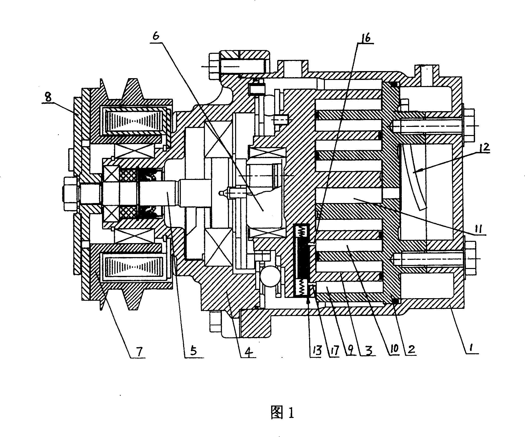
[0003] The purpose of the present invention is to solve the problems existing in the operation of the existing scroll air-conditioning compressors for vehicles, and to provide a variable displacement compressor by utilizing the characteristic that the scroll disk of the scroll compressor will generate centrifugal force during the movement process. The amount of centrifugal force controlled variable displacement scroll compressor to solve the problem of the stability of the cooling (heat) capacity of the existing automotive air conditioning system driven by the scroll compressor, so that the cooling (heat) of the air conditioning system Capability unaffected by changes in engine speed

Method used


Image

  • Centrifugal force control type variable displacement vortex type compressor
  • Centrifugal force control type variable displacement vortex type compressor

Examples


Embodiment 1

[0020] A centrifugal force-controlled variable-displacement scroll compressor, comprising a casing 1, a scroll-type static disk 2, a scroll-type moving disk 3, a front cover 4, a crankshaft 5, an eccentric sleeve 6, and a scroll-type static disk 2 Cooperate with the scroll-type moving disk 3 and install it in the casing 1, the scroll-type stationary disk 2 is fixed in the casing 1, the scroll-type moving disk 3 is connected with the eccentric sleeve 6, the eccentric sleeve 6 is connected with the crankshaft 5, and the crankshaft 5 is located in the front cover 4, the front cover 4 is connected with the housing 1, and the clutch pulley 7 is installed on the front cover 4, and the clutch pulley 7 drives the crankshaft 5 to rotate by driving the friction plate 8 installed on the crankshaft 5; the scroll type The static disc 2 cooperates with the scroll type movable disc 3 to form a crescent-shaped suction cavity 9, a crescent-shaped intermediate cavity 10, a crescent-shaped centra...

Embodiment 2

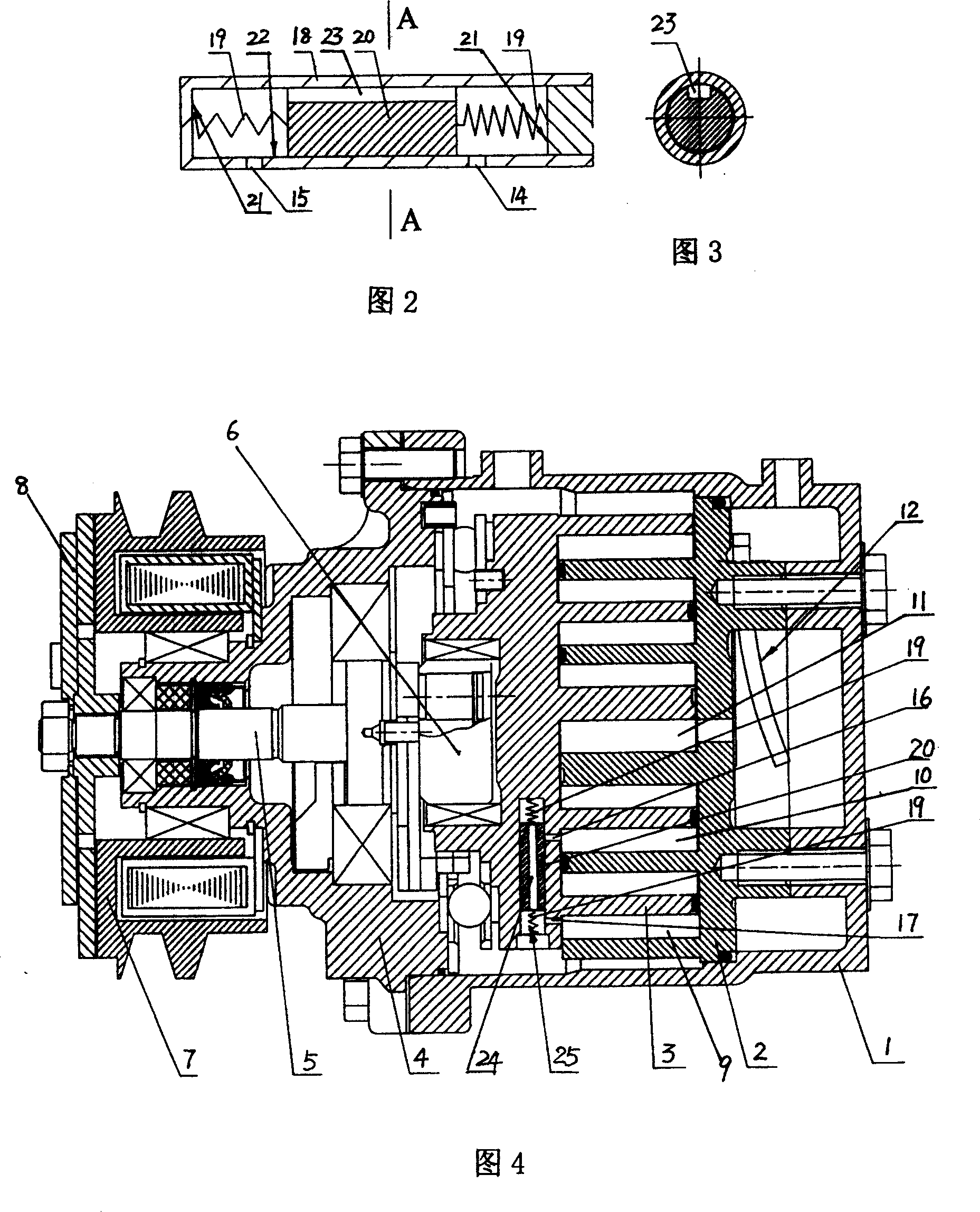
[0023] As shown in Figure 4.

[0024] A centrifugal force-controlled variable-displacement scroll compressor, comprising a casing 1, a scroll-type static disk 2, a scroll-type moving disk 3, a front cover 4, a crankshaft 5, an eccentric sleeve 6, and a scroll-type static disk 2 Cooperate with the scroll-type moving disk 3 and install it in the casing 1, the scroll-type stationary disk 2 is fixed in the casing 1, the scroll-type moving disk 3 is connected with the eccentric sleeve 6, the eccentric sleeve 6 is connected with the crankshaft 5, and the crankshaft 5 is located in the front cover 4, the front cover 4 is connected with the housing 1, and the clutch pulley 7 is installed on the front cover 4, and the clutch pulley 7 drives the crankshaft 5 to rotate by driving the friction plate 8 installed on the crankshaft 5; the scroll type The static disc 2 cooperates with the scroll type movable disc 3 to form a crescent-shaped suction cavity 9, a crescent-shaped intermediate cav...


PUM


Abstract

The centrifugal force controlled variable displacement vortex compressor has vortex static disc and vortex dynamic disc matched each other and installed inside the casing, and has also eccentric sleeve, front cover, and clutch belt wheel to drive the crankshaft. The vortex static disc and the vortex dynamic disc are matched to form crescent sucking cavity, crescent middle cavity, and crescent central cavity connected to the air inlet of the exhaust valve. The present invention features that at least one flow rate regulating valve is installed in the vortex dynamic disc and the flow rate regulating valve has its air inlet communicated with the crescent middle cavity or the crescent central cavity and discharge hole communicated with the crescent sucking cavity. The present invention alters the displacement of the vortex compressor mechanically and has the aadv of simple structure, convenient installation and reliable operation.

Description

technical field [0001] The invention relates to a scroll compressor, in particular to a centrifugal force controlled variable displacement scroll compressor. Background technique [0002] At present, relying on cars to travel is still an important way for people to go to get off work, get off work and travel. With the improvement of people's requirements for travel comfort, car air conditioners have become an essential function for various vehicles. Existing automobile air conditioner is a kind of air conditioning system driven by engine compressor. Scroll compressor is a kind of air-conditioning compressor that has developed very rapidly in recent years. It has the advantages of high speed, normal operation under the condition of less oil and no oil, long service life, convenient and simple maintenance, and has been widely used as Compressors for car air conditioners. The scroll compressor is generally directly driven by the main engine. In order to obtain a satisfactory ...

Claims


Application Information

Patent Timeline
Patent Type & Authority Patents(China)
IPC IPC(8): F04C28/26F04C18/02
Inventor 钱永贵易丰收
Owner ANHUI AOTECAR SCI & TECH DEV
Learn More