Francis wheel and hydraulic machine therewith

A runner and turbine technology, applied in the field of hydraulic machinery, can solve problems such as deterioration and unresearched

Inactive Publication Date: 2007-09-19
ALSTOM RENEWABLE TECH
View PDF10 Cites 0 Cited by
  • Summary
  • Abstract
  • Description
  • Claims
  • Application Information

AI Technical Summary

Problems solved by technology

In particular, in the case of retrofitting an existing installation, the rotational speed N 11 is set, which will actually limit the power value P that can be achieved by conventional turbines 11FC
[0006] [06] So far, hydraulic machinery designers have not really studied the equivalent power relative to the rotational speed N 11 Relationship

Method used


Image

  • Francis wheel and hydraulic machine therewith
  • Francis wheel and hydraulic machine therewith
  • Francis wheel and hydraulic machine therewith

Examples


Embodiment Construction

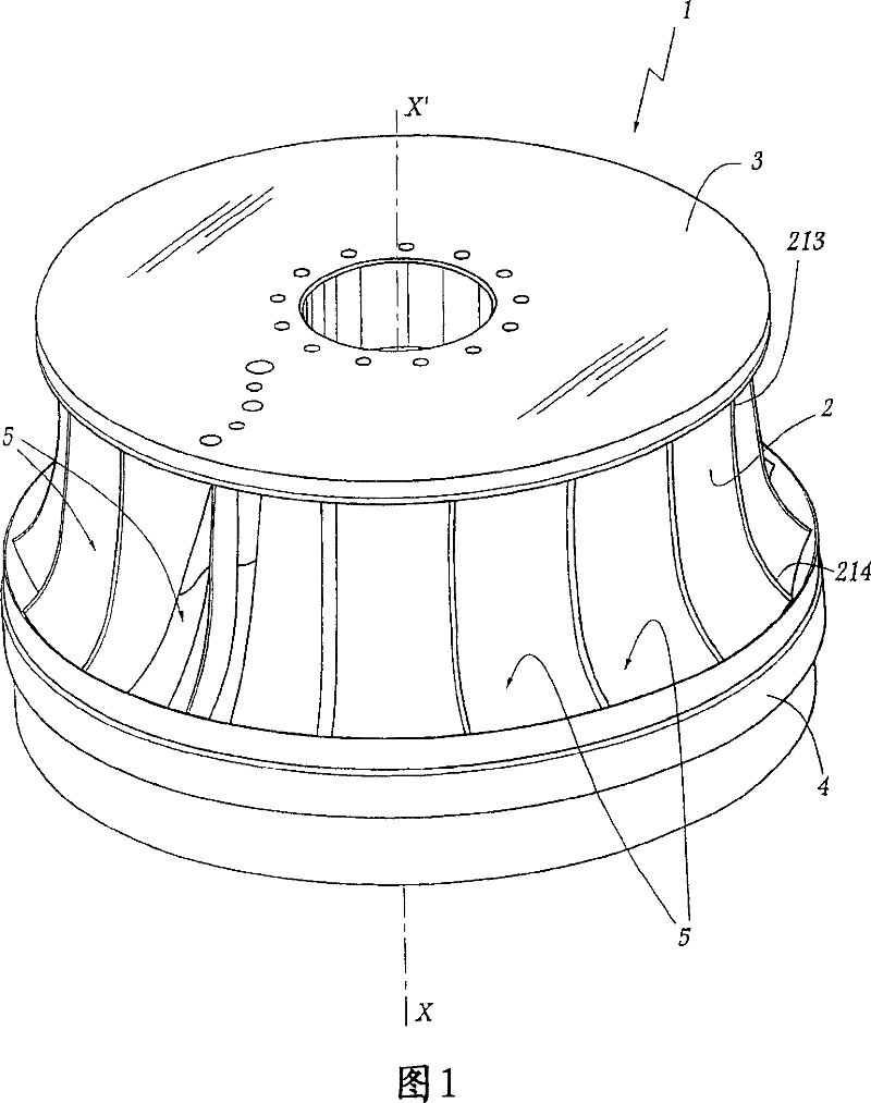
[0029] [29] The runner 1 shown in FIGS. 1 to 5 comprises a number of identical blades 2 distributed around the central axis of rotation X-X' of the runner 1 . A top plate 3 is arranged on the radially inner upper portion of the runner 1 , and the tire 4 is located on the edge of the radially outer lower portion of the blade 2 . Thus, a flow channel 5 is formed between each pair of adjacent blades, this channel being delimited by the top plate 3 and the rim 4 .

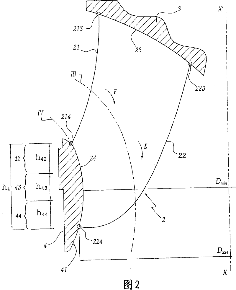
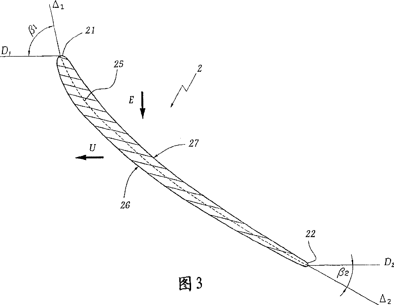
[0030] [30] Reference numeral 21 designates the flow edge of the blade 2 . 22 designates the runoff edge of the blade. 213 represents the joining point of the spoiler edge 21 and the top plate 3 . 214 represents the joining point of the spoiler edge 21 and the tire 4 . 223 refers to the joint point of the flow edge 22 and the top plate 3 , and the reference number 224 represents the joint point of the flow edge 22 and the tire 4 .

[0031] [31] Line III in FIG. 2 represents the meridian trajectory of the vortex of ...


PUM


Abstract

The Francis wheel, having a top, a ring and a series of blades (2) between them forming liquid flow ducts, has the angle between the linear velocity (U) of a blade's movement and the median line (25) of the blade at the level of its trailing edge close to the point (224) where the blade joins the ring is between 20 and 25 degrees. At the blade's leading edge the angle between the linear velocity and median line has a mean value of between 70 and 120 degrees.

Description

technical field [0001] [01] The present invention relates to a Francis type runner and a hydraulic machine equipped with the same. Background technique [0002] [02] Francis runners can be fitted to different types of hydraulic machinery, such as turbines, pumps, or pump turbines. Francis-type runners consist of vanes arranged around a central axis of rotation, between which channels are formed to allow the passage of water. The geometry of these runner blades is defined such that the water flow can generate a moment on the water turbine - in the case of a turbine, or transmit motion to the fluid - in the case of a water pump. The power output of a hydraulic machine equipped with this runner depends on its geometry and the type of chute associated therewith. In this way, the output power of the turbine is set as a reference value obtained from a turbine with the same geometry and a runner outlet diameter of 1 m under the condition of a water head of 1 m. The equivalent po...

Claims


Application Information

Patent Timeline
Patent Type & Authority Patents(China)
IPC IPC(8): F03B3/02F03B3/12
CPCF03B3/02Y10S416/02Y02E10/223F03B3/12Y02E10/20
Inventor F·帕凯B·米歇尔
Owner ALSTOM RENEWABLE TECH
Why Eureka
Try Eureka