Non contact rotatable electric energy transfer device

A power transmission, non-contact technology, applied in electromechanical devices, electrical components, irreversible AC power input into DC power output and other directions, can solve the problems of poor mechanical strength, limited rotation angle, low power, etc., to achieve a solid structure. Effect

Inactive Publication Date: 2007-10-24
DONGHUA UNIV
View PDF3 Cites 0 Cited by
  • Summary
  • Abstract
  • Description
  • Claims
  • Application Information

AI Technical Summary

Problems solved by technology

[0008] The technical problem to be solved by the present invention is to provide a non-contact rotatable electric energy transmission device to overcome the problems in the prior art that are easy to generate sparks, Defects such as limited rotation angle, low power, poor mechanical strength and unstable voltage amplitude

Method used


Image

  • Non contact rotatable electric energy transfer device
  • Non contact rotatable electric energy transfer device
  • Non contact rotatable electric energy transfer device

Examples


Embodiment Construction

[0024] The present invention will be described in detail below in conjunction with the accompanying drawings and specific embodiments.

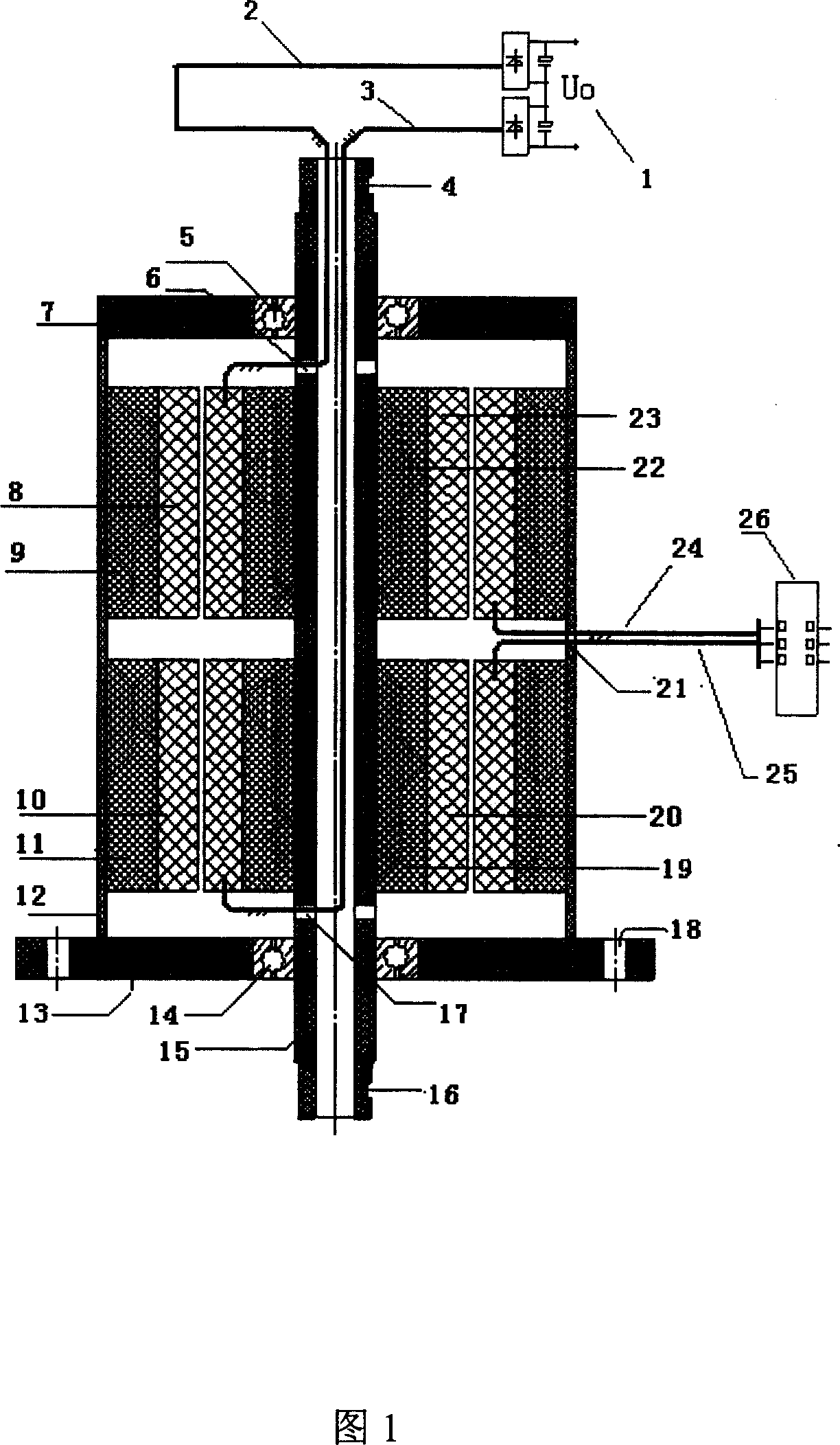
[0025] As shown in the figure, the present invention includes a casing, a rotating shaft, a stator, a rotor, an input power supply, and an output circuit. Both the stator and the rotor are embedded with three-phase windings. The stator and the rotor are divided into upper and lower sets and coaxially installed in the casing. With the alternating current of opposite phase sequence, the outputs of the two rotors are superimposed in series after passing through the rectifier circuit respectively.

[0026] In Fig. 1, the device has an upper end cover and a lower end cover, and bearings for fixing the rotor are installed on the cover; threading holes are opened on the inner walls at both ends of the rotating shaft for the three-phase lead wires of the rotor to pass through, between the upper and lower sets of stator and rotor There are also thread...


PUM


Abstract

The invention discloses a non-contact rotary electric energy transmitting device, which includes a shell, a spindle, a stator, a rotor, input power and output circuit, the stator and the rotor are arranged with triphase windings, the character lies in: there have two sets of stator and rotor which are assembled in the shell coaxially, the spindle is hollow, wire apertures are arranged on the shell and the side walls of the spindle. The triphase output wire of the input and output circuit are leaded out from the aperture; the two stators are supplied with alternate current with the reversal phase, the output of the two rotors are overlapped in series after passing the commutating circuit. The merits are: it is coaxial double stator and double rotor structure, the series overlapping of output potential and conducting with the reverse phase alternate current, the torque generated by the two rotors is equal, the direction is reverse, which two can be counteracted, it will not rotate automatically, it can rotate angle with outer driving mechanism, and the voltage fluctuation, thus, it realizes to transmit the electric energy on stator side to rotary rotor side in non-contact way.

Description

technical field [0001] The invention belongs to the electric energy transmission technology, and in particular relates to a non-contact rotatable electric energy transmission device for providing electric energy to a rotating mechanical part. Background technique [0002] For devices that supply power to rotating moving parts, the following designs are generally used: [0003] (1) The electric energy is transmitted to the shaft through contact with the slip ring on the shaft through the brush. The device is prone to sparks due to its contacts, and is not suitable for exposure-proof environments and other harsh environments, and is subject to wear and tear. [0004] (2) The electric energy is transmitted by contacting the brush with the metal ring on the plane of the turntable, the disadvantage is the same as (1). [0005] (3) Existing non-contact devices such as resolvers are mainly used for angle measurement, because as the angle changes, the voltage amplitude coupled to ...

Claims


Application Information

Patent Timeline
Patent Type & Authority Patents(China)
IPC IPC(8): H02M7/30H02K16/00
Inventor 吴庆彪孙培德
Owner DONGHUA UNIV
Why Eureka
Try Eureka