Cross anti-pitch rudder

A cross-shaped, pitching technology, which is applied to steering gear, rudder steering, ships, etc., can solve problems that have not yet been discovered, achieve the effect of reducing ship pitching motion, requiring no operating costs, and broad application prospects

Inactive Publication Date: 2007-11-14
SHANGHAI JIAOTONG UNIV
View PDF5 Cites 0 Cited by
  • Summary
  • Abstract
  • Description
  • Claims
  • Application Information

AI Technical Summary

Problems solved by technology

In further searches, no literature reports identical or similar to the subject of the present invention have been found so far

Method used


Image

  • Cross anti-pitch rudder
  • Cross anti-pitch rudder
  • Cross anti-pitch rudder

Examples


Embodiment Construction

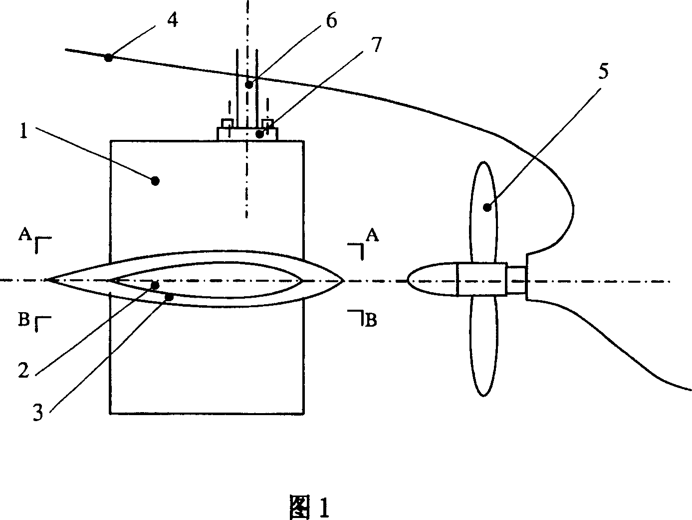
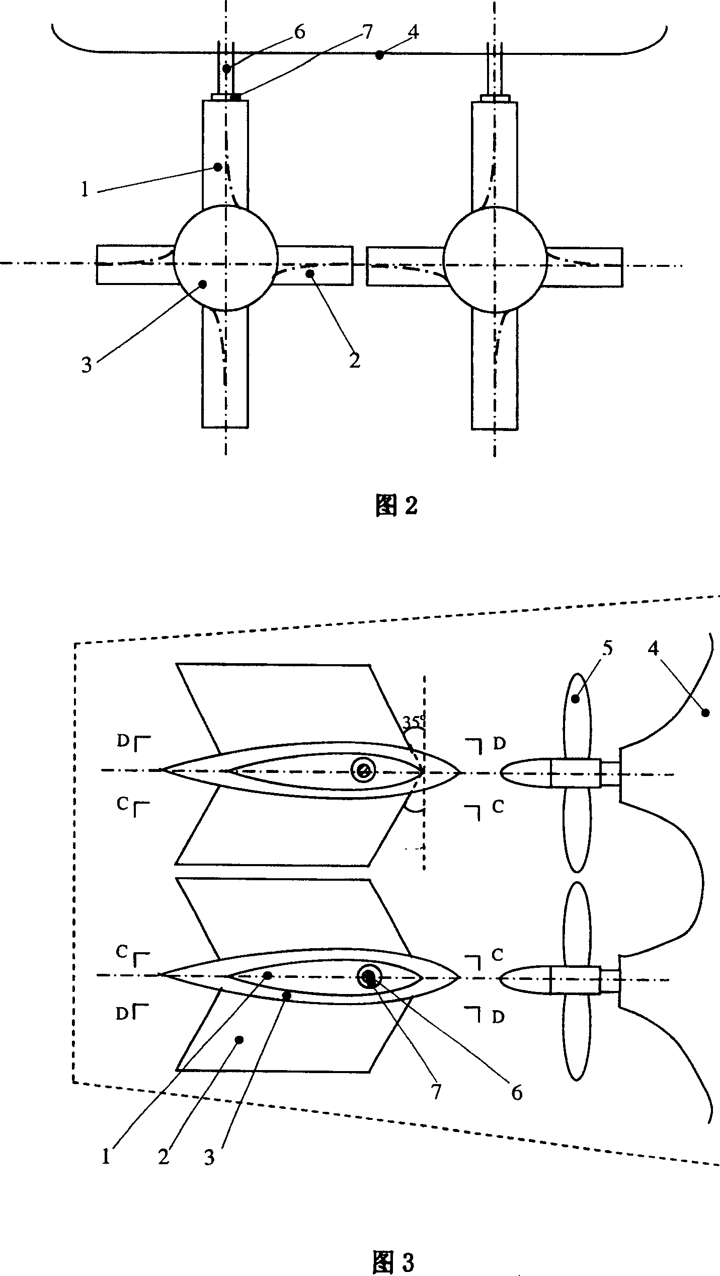
[0017] The invention has a wide range of applications. Divided according to the number of rear oars and rudders, it is suitable for single oar single rudder boats, double oar double rudder boats and multi oar multi rudder boats; according to the rudder support method, it is suitable for suspended rudders, semi suspended rudders and supporting rudders ; According to the position of the rudder shaft, it can be applied to balanced rudders or unbalanced rudders with rudder posts in front of the rudder. The technical solution of the present invention will be further described below in conjunction with the embodiments and accompanying drawings of a ship with double propellers and double suspended rudders (that is, a ship with two propellers and two rudders installed).

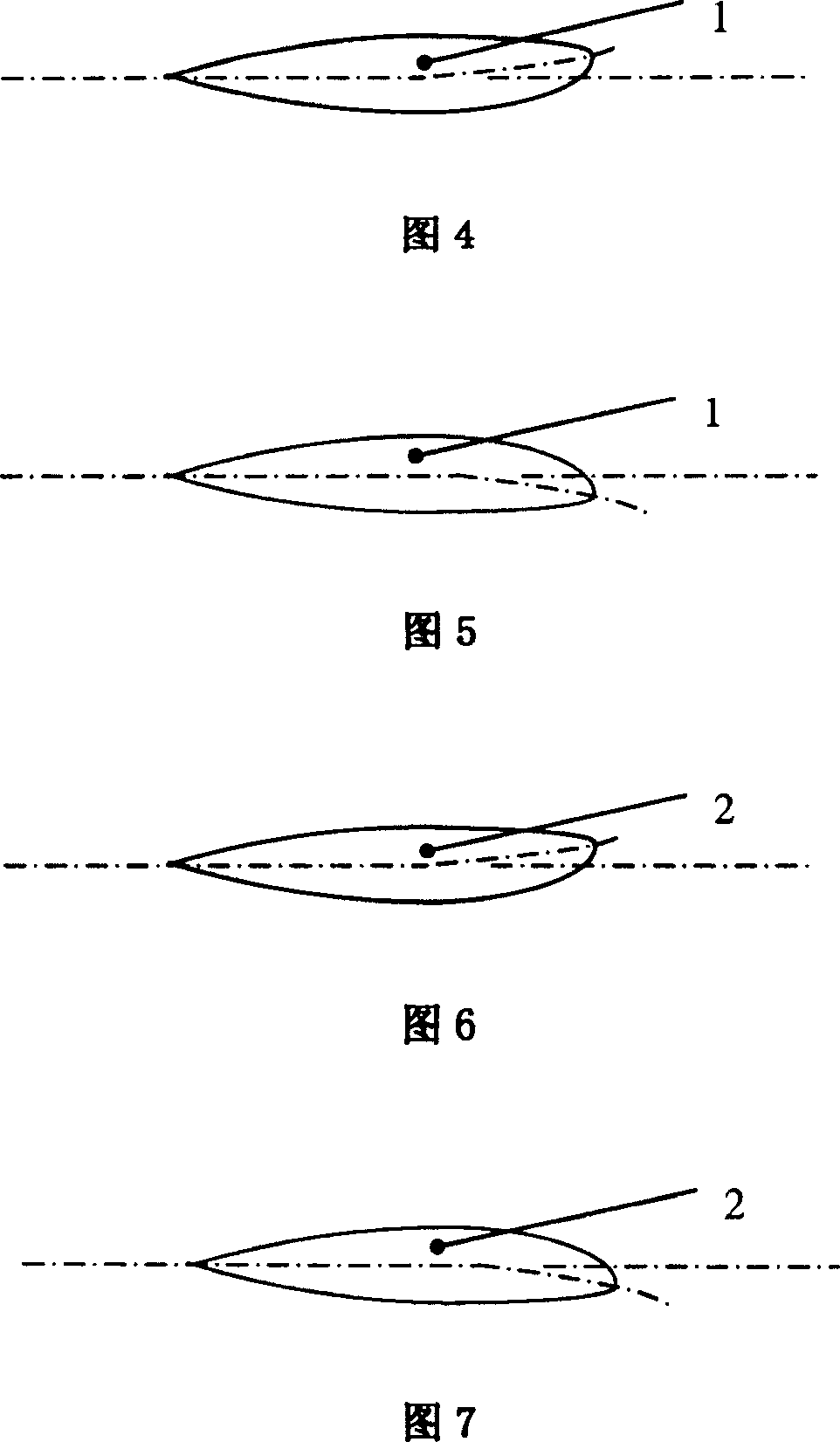
[0018] Each single cross-type anti-pitch rudder of the present invention is welded by a vertical reaction rudder blade 1, a horizontal reaction rudder blade 2 protruding vertically from both sides of the vertical rea...


PUM


Abstract

The invention relates to a crossed anti-vertical rocking rudder, belonging to ship and ocean engineering technical field, composed of a vertical response rudder blade, a horizontal response rudder blade and intersection streamline rudder ball and installed at back of tail screw propeller of a ship and adjacent to the tail screw propeller. The invention effectively reduces vertical shaking motion of the ship body in waves, especially by a large margin reducing vertical shaking amplitude of the ship body approaching to resonance state, and completely improving wave resisting performance of a large-scale water surface ship. It can hang, semi-hang and support a rudder, applied to a single- paddle single-rudder ship, a double-paddle double-rudder ship and a multi-paddle multi-rudder ship. It can be used in designing a new ship and reconstructing and improving the wave resisting performance for the active water surface ships on condition of not changing the structures of the main ship bodies, thus having a completely wide spreading and applying prospect.

Description

technical field [0001] The invention relates to a device in the technical field of ships, in particular to a cross-shaped anti-pitch rudder. Background technique [0002] In order to reduce the swaying motion of the ship and improve the seakeeping performance of the ship, most ships have bilge keels arranged along the length of the underwater hull bilge, and some ships are equipped with anti-rolling tanks or fins. The bilge keel has a simple structure and low cost, but the anti-rolling effect is not ideal at low speeds, which increases the navigation resistance; the anti-rolling water tank not only needs to occupy the effective volume of the cabin, which increases the operating cost, but also has poor roll attenuation effect; the anti-rolling fin is An active anti-rolling device has a good anti-rolling effect when sailing at high speed, but basically cannot achieve the effect of anti-rolling when sailing at low speed or no speed, and the structure is complex and expensive, a...

Claims


Application Information

Patent Timeline
Patent Type & Authority Patents(China)
IPC IPC(8): B63H25/38
CPCB63H2025/388
Inventor 缪国平朱仁传范佘明
Owner SHANGHAI JIAOTONG UNIV
Why Eureka
Try Eureka