Electroluminescent diode panel mould set with separated casing

An electro-luminescence, panel mold technology, applied in the direction of electrical equipment shell/cabinet/drawer, electrical components, electrical equipment structural parts, etc., to achieve the effect of helping product yield and efficiency

Active Publication Date: 2007-12-05
테스콤가부시키가이샤
View PDF4 Cites 0 Cited by
  • Summary
  • Abstract
  • Description
  • Claims
  • Application Information

AI Technical Summary

Problems solved by technology

[0009] Therefore, in the process of electroluminescence panel modules (such as OLED panel modules or PLED panel modules), the assembly step of the metal base plate 20 belonging to the end of the process, although it is a step with relatively low technical difficulty, However, there is a hidden threat to the entire process. For the rese

Method used


Image

  • Electroluminescent diode panel mould set with separated casing
  • Electroluminescent diode panel mould set with separated casing
  • Electroluminescent diode panel mould set with separated casing

Examples


Embodiment Construction

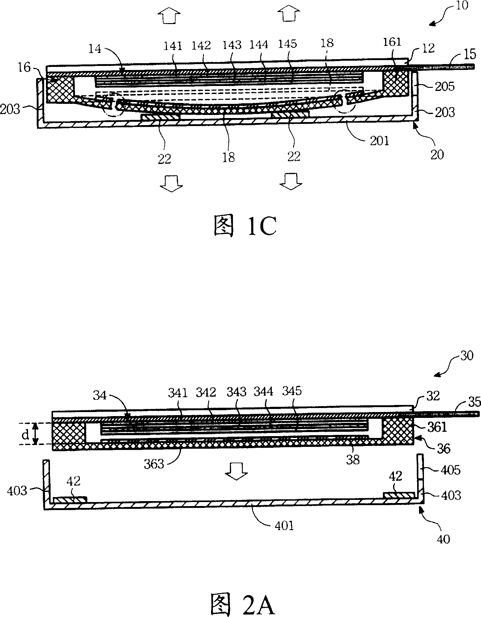
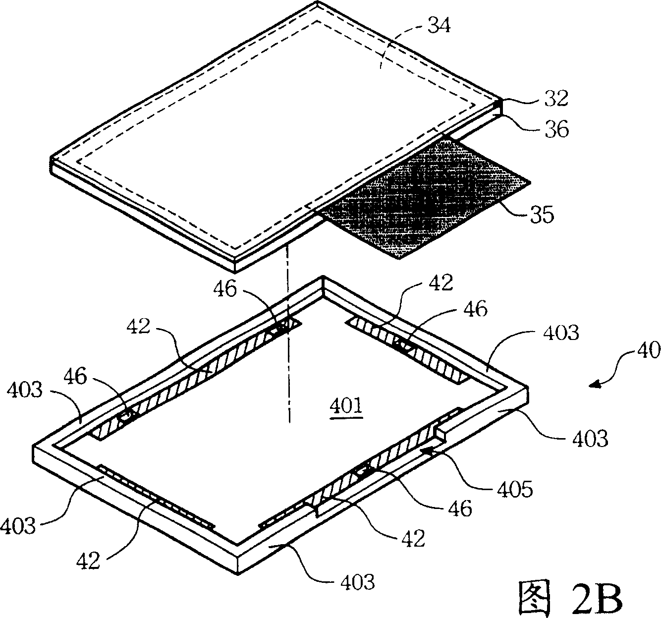
[0042] Please refer to FIG. 2A . FIG. 2A is a side sectional view of the electroluminescence panel module of the present invention. The electroluminescent body panel module 30 includes a substrate 32 , an electroluminescent body 34 , a casing 36 , and a casing 40 . The casing 36 includes a casing surface 363 and a connecting portion 361 extending from the upper surface of the casing surface 363 , and the casing 36 forms an accommodating space with the substrate 32 through the connecting portion 361 . The electroluminescent body 34 is disposed on the surface of the substrate 32 and located in the accommodating space. The shell 40 is combined with the casing 36 through an adhesive element 42 . Wherein, the adhesive element 42 is disposed on the lower surface of the shell surface 363 in a range corresponding to the connecting portion 361 .

[0043]Wherein, the height of the connecting portion 361 (height d indicated in FIG. 2A ) is between 0.1 mm˜0.5 mm. A desiccant 38 can be ...


PUM

PropertyMeasurementUnit
Heightaaaaaaaaaa

Abstract

The invention consists of a base plate, a case, an Electro Luminescent and a shell. The case consists of a case surface and a connecting part extending from surface of case. Through the connecting part a holding space is formed between the case and the base plate. The Electro Luminescent is set in the surface of the base plate and is held in the holding space. The shell is united with the case through a binding component. The binding component is set in the area under the surface of case and corresponding to the connecting part.

Description

technical field [0001] The present invention relates to an electroluminescence panel module, in particular to an electroluminescence panel module with a detachable shell. Background technique [0002] Organic electroluminescence diode panel module (hereinafter referred to as OLED panel module) is a display element with high brightness, high response speed, light weight, short size, full color, no viewing angle difference and no backlight, so it has taken the lead in replacing TN (Twisted Nematic) and STN (Super Twisted Nematic) LCD panel module market, and will further pose a threat to the market for small-sized TFT-LCDs, and are used in mobile phones, personal digital assistants, and even notebook computers and other portable information products on the display screen. [0003] Please refer to FIG. 1A , which is a side sectional view of a conventional OLED panel module. In the OLED panel module 10, an organic electroluminescent diode 14 is formed on the lower surface of a...

Claims


Application Information

Patent Timeline
IPC IPC(8): H05K5/00H05K7/00G09F9/00G09F9/30
Inventor 宋朝钦
Owner 테스콤가부시키가이샤
Why Eureka
Try Eureka