Realize the processing technology and fixture structure of multi-material substrates with simultaneous printing and patching

A technology of substrates and fixtures, applied in printing, printing machines, rotary printing machines, etc., can solve the problems of difficult matching of the number of substrates, low production efficiency, waste of production materials, etc., and achieve balance of processing volume, cost saving, and production reduction cost effect

Active Publication Date: 2017-02-08
WUXI CHINA RESOURCE MICRO ASSEMBLY TECH
View PDF6 Cites 0 Cited by
  • Summary
  • Abstract
  • Description
  • Claims
  • Application Information

AI Technical Summary

Problems solved by technology

[0004] It can be seen from the above process flow that the two substrates need to be processed separately and cannot be processed at the same time. Therefore, more equipment resources need to be configured during production, some equipment is used for DBC processing, and the other part is used for PCB processing, so that the efficiency can be improved accordingly. , but the input cost of the equipment is relatively high, or the equipment needs to be converted frequently, sometimes producing DBC, sometimes converting to PCB, the production efficiency is low, and the number of various substrates is difficult to match, mainly because a material is required first Production, used as preparation materials, and because of some uncertain factors in production, it is difficult to ensure the consistency between the preparation materials and the materials produced later, so there are more inconveniences in the production arrangement of the two materials, and it is easy to cause waste of production materials

Method used


Image

  • Realize the processing technology and fixture structure of multi-material substrates with simultaneous printing and patching
  • Realize the processing technology and fixture structure of multi-material substrates with simultaneous printing and patching
  • Realize the processing technology and fixture structure of multi-material substrates with simultaneous printing and patching

Examples


Embodiment 1

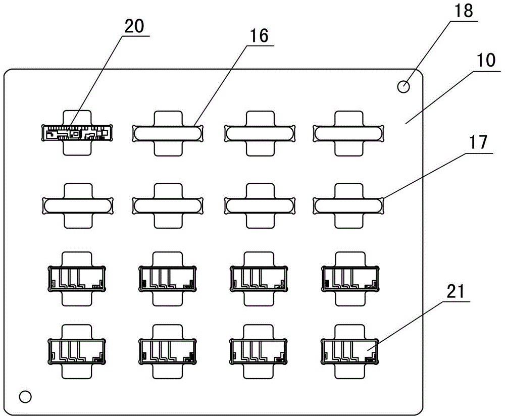
[0040] Embodiment one: see Figure 1~3 As shown, a jig structure that realizes the simultaneous printing and patching process of multiple material substrates, including bearing jigs, vacuum jigs and printing screens, wherein:

[0041] The carrying jig includes a body 10, which is provided with several kinds of substrate positioning grooves 16, the number of each substrate positioning groove 16 matches the ratio of the number of substrates corresponding to the product demand, and the bottom of the substrate positioning groove 16 open with through holes;

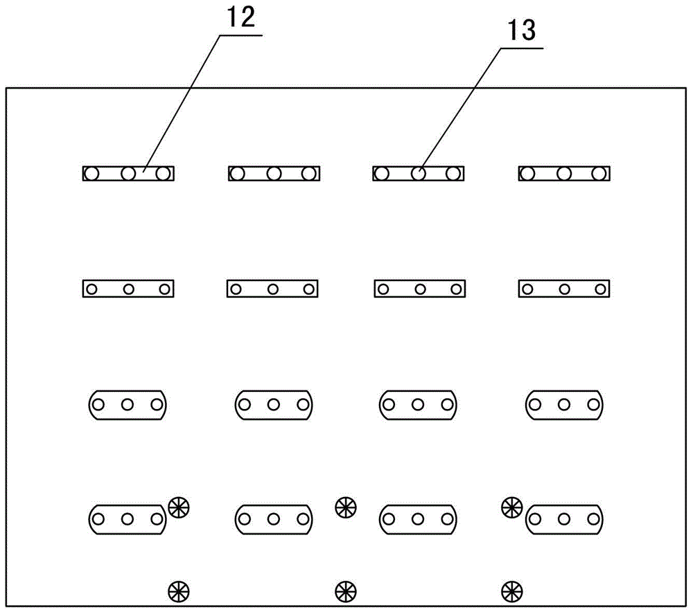
[0042] The vacuum jig is used in conjunction with the carrying jig, and it includes a support column 12 corresponding to each of the substrate positioning grooves 16, and each support column 12 is provided with several vacuum holes 13;

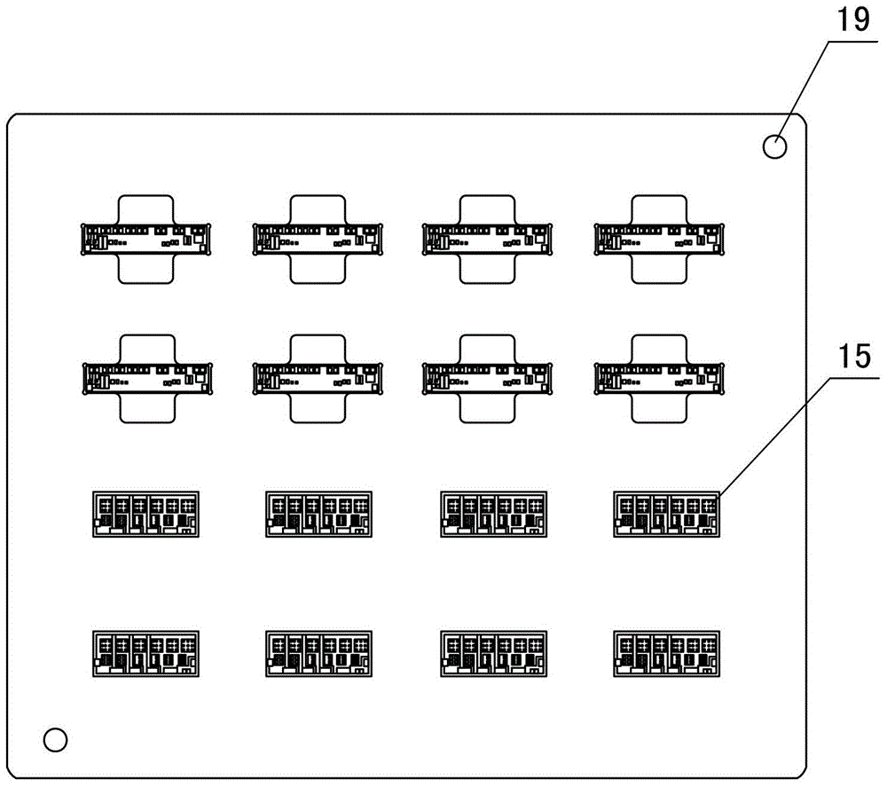
[0043] The printing screen is used in conjunction with the carrying jig, and corresponding to each of the substrate positioning grooves 16, there are several mesh holes 15 corresponding to th...

Embodiment 2

[0059] Embodiment two: see Figure 4 As shown, a multi-material substrate simultaneously prints a patch process and its jig structure. In this embodiment, its jig structure and process are similar to those of Embodiment 1. The difference lies in: the PCB substrate 30 required for the product One, one DBC substrate 31, the number of the two required is 2:1, so there are 10+5 substrate positioning grooves 32 on the carrying fixture, the upper two rows are 5+5 PCB substrate positioning grooves, and the lower row There are five DBC substrate positioning grooves. Similarly, the positions of the support columns on the vacuum jig and the mesh holes on the printing screen are matched with the substrate positioning grooves on the carrying jig to achieve simultaneous printing.


PUM


Abstract

The invention discloses a machining technology for conducting printing and surface mounting on substrates made of various materials simultaneously and a jig structure thereof. The jig structure comprises a bearing jig, a vacuum jig and a printing silk screen, wherein the bearing jig comprises a body, a plurality of kinds of substrate positioning grooves are formed in the body, the number of each kind of substrate positioning grooves is matched with the number of substrates corresponding to the product requirement, the vacuum jig is located below the bearing jig and comprises supporting columns, the number of the supporting columns corresponds to the number of the substrate positioning grooves, a plurality of vacuum holes are formed in each supporting column, the printing silk screen comprises a silk screen body, and a mesh used for tinning of a product located at the corresponding position is arranged at the position, corresponding to each substrate positioning groove, of the silk screen body. According to the machining technology for conducting printing and surface mounting on the substrates made of various materials simultaneously and the jig structure thereof, printing and surface mounting are conducted on all kinds of substrates simultaneously by placing the substrates on the bearing jig, then assembling, returning and cleaning are conducted, the production technology is simplified, the production efficiency is improved effectively, material balance is achieved, waste is reduced, and cost is reduced.

Description

technical field [0001] The invention relates to a substrate printing process, in particular to a processing technology and a jig structure for simultaneously printing patches on multiple material substrates. Background technique [0002] Solder paste printing in the traditional SMT industry is often printed on the substrate of the same material (such as PCB). However, with the evolution of high integration of electronic products, some devices need to use more than two different materials and substrates, such as DBC substrate (Dircet Bonding Copper), direct copper-clad substrate, is another substrate material different from PCB substrate. It has excellent electrical insulation and thermal conductivity characteristics, and is often used as the carrier of silicon chips in power modules. [0003] Taking smart power modules as an example, some modules integrate DBC boards and PCB boards. In the processing process, printing and patching are required on these two substrates. The cu...

Claims


Application Information

Patent Timeline
Patent Type & Authority Patents(China)
IPC IPC(8): B41F15/08B41M1/12
Inventor 刘晓明吴俊魏元华杨文波龚平
Owner WUXI CHINA RESOURCE MICRO ASSEMBLY TECH
Why Eureka
Try Eureka