
Intelligent integrated solar energy navigation mark lamp

A technology of solar energy and navigation lights, which is applied in navigation route marking, water-based ship navigation equipment, lighting and heating equipment, etc., can solve the problems of normal development of waterway management and hidden dangers of shipping safety, non-compliance with waterway management departments, low processing efficiency, etc. problems, to achieve the effect of low construction and maintenance costs, perfect fault-tolerant mechanism, and simple structure

Inactive Publication Date: 2007-12-26
广东省广州航道局城区航道分局 +1
View PDF8 Cites 0 Cited by
  • Summary
  • Abstract
  • Description
  • Claims
  • Application Information

AI Technical Summary

Problems solved by technology

If the detection cycle is missed, once the beacon light fails, it will not be repaired until the next inspection, which brings great hidden dangers to the normal development of channel management and shipping safety.
Taking Guangdong as an example, the current maintenance work of the navigation lights still uses the original set, and the inspection cycle is 7 days, with a total of 52 voyages per year. Regardless of whether the equipment is actually damaged or not, maintenance is carried out according to a fixed schedule. This method wastes a lot of manpower and material resources when the equipment is not damaged, but once the equipment fails and affects the use, it may take a long time to know the problem because of the inspection sequence
On the other hand, the problem of the deviation of the navigation light is very prominent. At present, the deviation of the navigation mark can only be adjusted and corrected during routine inspection. The efficiency of timely processing after the problem occurs is very low.
However, when the navigation lights deviate, it will bring danger to the ships navigating on the waterway, which does not meet the needs of the waterway management department.

Method used


Image

  • Intelligent integrated solar energy navigation mark lamp
  • Intelligent integrated solar energy navigation mark lamp

Examples


Embodiment Construction

[0017] The present invention will be further described below in conjunction with the accompanying drawings and embodiments.

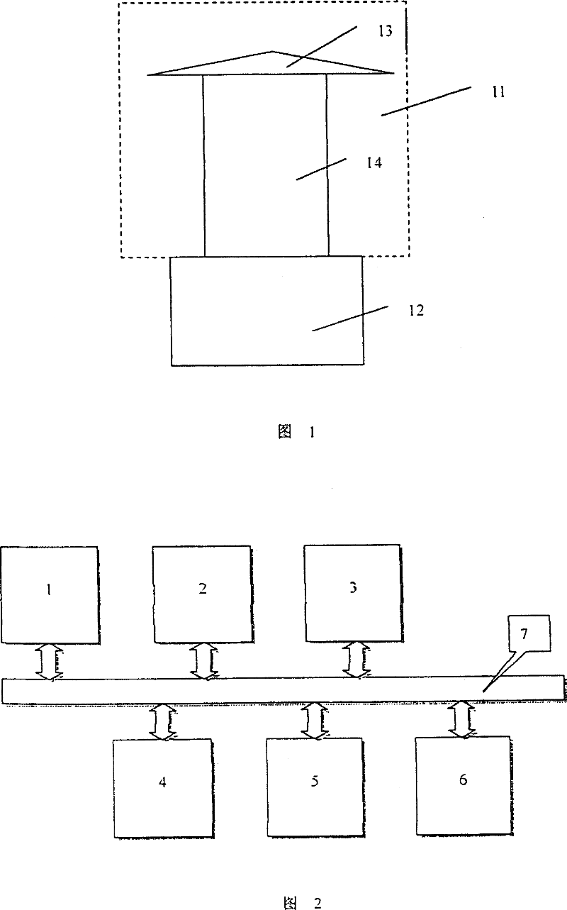
[0018] As shown in FIG. 1 , the present invention includes a lamp lens 11 and a base 12 . The lamp lens 11 is made up of a top cover 13 and a convex lens 14 (the dotted line indicates that the combination of the top cover 13 and the convex lens 14 constitutes the lamp lens 11), and the lamp base 12 is placed at the bottom of the convex lens 14, wherein the top cover 13 and the convex lens 14 are independent The components are tightly connected by a tapered seam. The top cover 13 has a built-in solar cell assembly 1, and can be replaced with a replacement top cover of different specifications (that is, a solar cell assembly of a different specification) according to different power requirements. The sealed connection between the lamp lens 11 and the lamp base 12 is a screw-type connection with an undercut and a downward pressure. The flash cycle of the...


PUM


Abstract

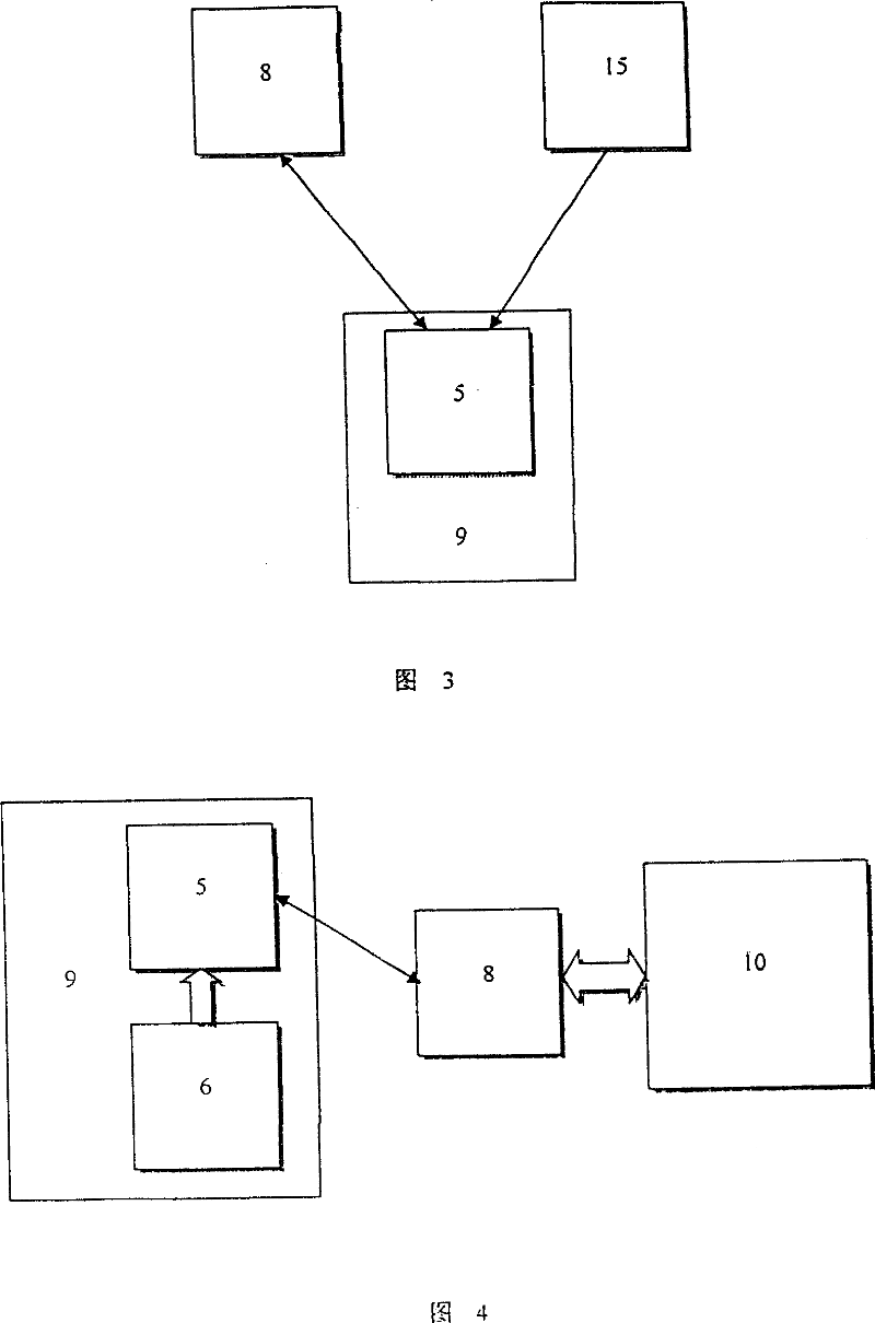
The invention relates to an intelligent integrated solar energy navigation mark lamp, which is comprised by lamp lens, subbase and function control module. It is characterized in that: the function control module is comprised by solar cell, maintenance-free accumulator, LED electric light source, lamp control module, satellite positioning and wireless communication module, electric detection module, the said all function modules are connected via bus and are integrated and sealed together in the lamp comprised by the lamp lens and the subbase. The invention utilizes wireless networks to transfer satellite positioning signal and network positioning correcting signal, and transmits accurate positioning information and navigation mark lamp electric parameter obtained by the electric detection module to control center via wireless network. The invention has advantages of simple and compact structure, perfect performance, low energy consumption, convenience for maintenance, low construction and maintenance cost, thus, it is widely applicable for sea-route management field.

Description

Technical field [0001] The invention relates to the technical and structural improvement of a solar navigation beacon light, in particular to an intelligent integrated solar navigation beacon light. Background technique [0002] At present, the navigation lights used in China do not have any automatic detection and positioning functions, and the waterway management department can only regularly arrange personnel to conduct on-site inspections of the navigation lights. If the inspection cycle is missed, once the beacon light fails, it will not be repaired until the next inspection, which brings great hidden dangers to the normal development of waterway management and shipping safety. Taking Guangdong as an example, the current maintenance work of the navigation lights still uses the original set, and the inspection cycle is 7 days, with a total of 52 voyages per year. Regardless of whether the equipment is actually damaged or not, maintenance is carried out according to a fix...

Claims


Application Information

Patent Timeline
IPC IPC(8): B63B51/00F21S9/03H04Q9/00
Inventor 李月楼李德敏赖永福阮广德周劲斌温炳文罗明华李水新张业兰陈燕嫦
Owner 广东省广州航道局城区航道分局
Learn More