Backlight module structure

A technology of backlight module and light guide plate, which is applied in the direction of optics, nonlinear optics, diffuser elements, etc., and can solve problems such as black tape falling off, light concentrated at the position of the lug, and unfavorable for mass production.

Active Publication Date: 2008-01-16
AU OPTRONICS CORP
View PDF6 Cites 0 Cited by
  • Summary
  • Abstract
  • Description
  • Claims
  • Application Information

AI Technical Summary

Problems solved by technology

However, when using this method for light projection, it is found that the light is often concentrated at the rectangular right-angle position 100a or 100b, because when the light reaches the lug of the light guide plate, part of the light will be refracted, and part of the light will penetrate to reach The frame of the module is refracted back to the edge of the light guide plate, and the missing light will be refracted back and forth between the frame and the light guide plate, resulting in the phenomenon that the light is concentrated at the position of the lug
[0006] In order to improve this shortcoming, U.S. Patent No. 5,988,827 discloses a method of modifying the angle of the lug angle of the plastic frame in the backlight module to improve the refraction of light, in which the original right-angle part is modified into an arc to guide light The light refracted to the lug is shown in Figure 2, but after modifying the angle of the arc-shaped lug 300, not only the angle of the light guide plate must be modified, but also the groove of the frame must be modified accordingly, which is time-consuming to manufacture and is not conducive to mass production
[0007] U.S. Patent No. 6,561,664 discloses a method of attaching a black adhesive tape 400 at the position of the groove 201 of the module frame 200, as shown in FIG. The missing light is absorbed; however, the black tape tends to peel off after prolonged use, and engineering reliability will also be affected

Method used


Image

  • Backlight module structure
  • Backlight module structure
  • Backlight module structure

Examples


Embodiment 1

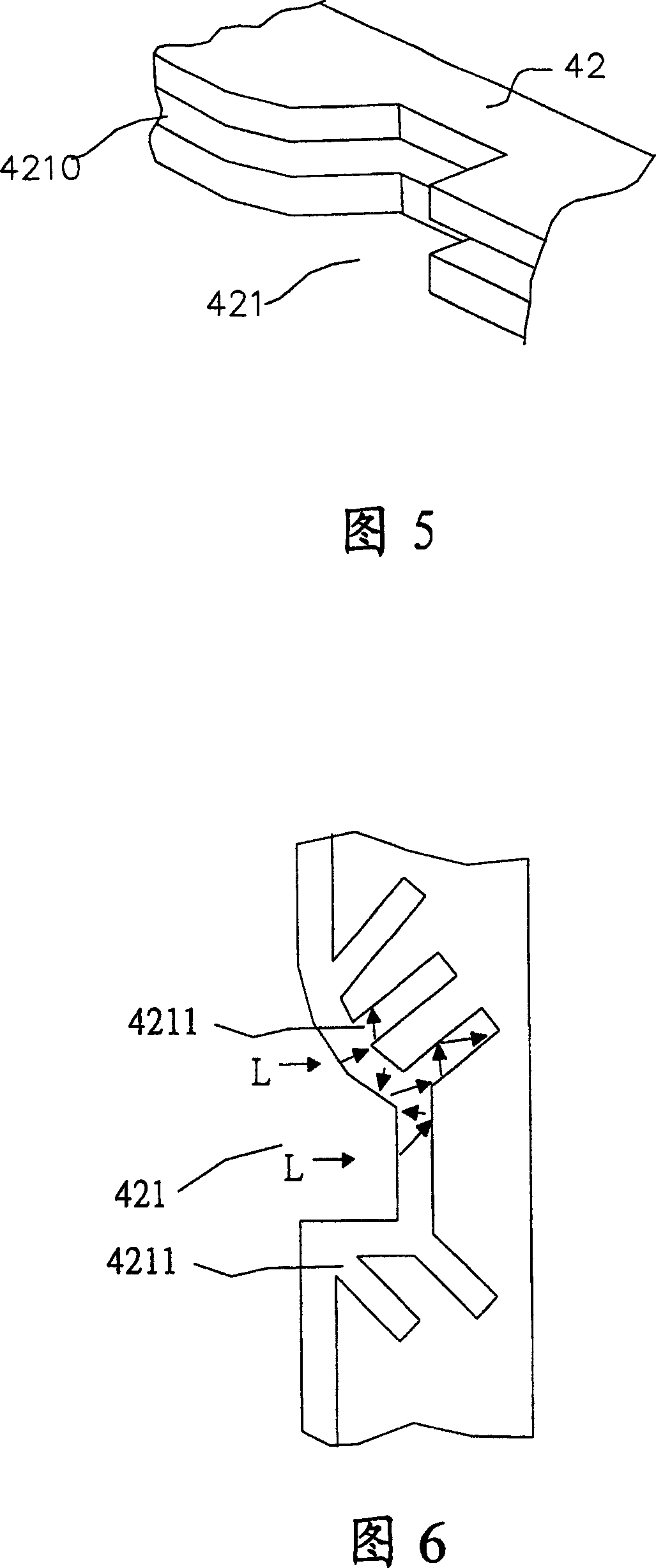
[0039] As shown in 5, the light guiding device is a groove 4210 arranged on the frame 42. The groove 4210 is opened along the frame 42. When the light scattered by the reflector reaches the groove 421 or any position of the frame 42, such as from In the L direction, the light will be diffused along the groove 4210 at this time, and will not be reflected back to the reflector, so that the situation where the light at the lug of the reflector is particularly bright can be avoided.

Embodiment 2

[0041] As shown in Figure 6, the light guiding device is a groove 4211 arranged near the groove 421 of the frame, mainly at the position where light is easily reflected back to the reflector, and is set inside the frame 42, forming a vertical or non-perpendicular angle with the frame Open; when the light scattered by the reflector reaches any position of the groove 421 or the frame 42, such as from the L direction, the light will be guided out along the groove 4211 and will not be reflected back Reflective plate.

Embodiment 3

[0043]As shown in Fig. 7, in this embodiment, the light guide device is not only arranged on the frame of the backlight module, but also arranged on the outer frame 43 used for fixing the frame 42, and the half part on the dotted line in Fig. Sectional view of the interior; half of the dotted line is a top view of the light guide device.

[0044] The light guide device is arranged in the groove 4212 near the groove 421 of the frame, mainly at the position where light is easily reflected back to the reflector, and is set inside the frame 42, runs through the frame 42, and the groove 4212 is perpendicular to the frame 42 Or non-perpendicular angle; when the light scattered by the reflector reaches any position of the groove 421 or the frame 42, such as from the L direction, the light will be guided out along the groove 4212 and always be exported At the same time, in order to prevent light from encountering the plane of the outer frame 43 and being reflected back along the origi...


PUM


Abstract

This invention relates to an aphototropism module, which comprises at least one light source unit with one emitting source and one reflection pad; one light conductive plate with at least one handle in its circle located by side of the source unit; one base plate and one frame shell, wherein, the frame is located on the circle of base plate and the handle of the light conductive has one flute and multiple light conductive mechanism. This invention also comprises one aphototropism module shell, which comprises one base plate and one frame around the circle of the base plate one flute and multiple light conductive mechanisms around the frame.

Description

technical field [0001] The invention relates to a backlight module structure, in particular to a backlight module structure suitable for a liquid crystal display device. Background technique [0002] The flat-panel display industry has developed rapidly in recent years. In order to better improve the performance of the display, manufacturers are committed to the improvement and design of the structure of each device, and the backlight module in the liquid crystal display is moving towards the direction of providing a high-uniform, high-brightness light source. Improve. [0003] Since the liquid crystal itself does not emit light, a backlight (mostly fluorescent tubes) must be added behind the liquid crystal display panel. After the light source is projected, it first passes through a polarizer and then passes through the liquid crystal. Changes in the liquid crystal molecules to change the arrangement of the liquid crystal, and then change the angle of light penetrating the...

Claims


Application Information

Patent Timeline
Patent Type & Authority Patents(China)
IPC IPC(8): G02F1/1335G02B5/02
Inventor 黄资峰朱俊杰
Owner AU OPTRONICS CORP
Why Eureka
Try Eureka