

Rotary head and magnetic recording/reproducing device
A technology of rotating head and adjusting device, applied in the field of rotating head to avoid excessive impact or friction
- Summary
- Abstract
- Description
- Claims
- Application Information
AI Technical Summary
Problems solved by technology
Method used
Image

Examples
Embodiment approach 1
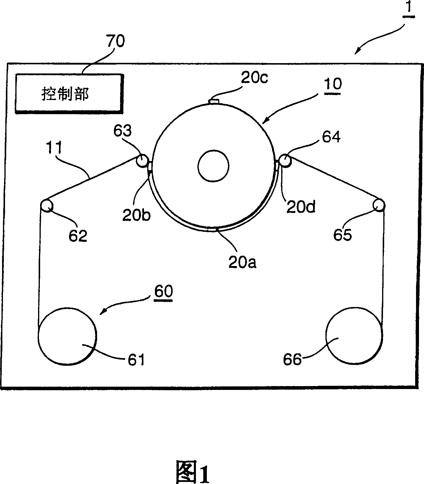
[0060] FIG. 1 is a schematic diagram showing a magnetic recording and reproducing apparatus 1 of this embodiment. The magnetic recording and reproducing device 1 records information or reads information on a magnetic tape 11 as a recording medium, and corresponds to, for example, a data storage for server backup, a portable cam camera, a video movement, and an audio movement. The magnetic recording and reproducing apparatus 1 includes a rotary head 10 equipped with a plurality of magnetic heads 20a to 20d; a transport mechanism 60 that transports a magnetic tape around the rotary head; and a control unit 70 that manages the overall operation of the apparatus.
[0061] The transport mechanism 60 includes, in order from the upstream of the movement of the magnetic tape 11, a feed reel 61 that supplies the magnetic tape 11 to the rotary head 10, a guide roller 62, and guide rollers 63, 64, and guide rollers arranged at positions where the magnetic tape 11 is bent toward the rotary he...
Embodiment approach 2
[0080] Hereinafter, embodiments of the present invention will be described with reference to FIGS. 7 to 10. In addition, the magnetic recording and reproducing device can be applied to the same device as that shown in FIG. 1.
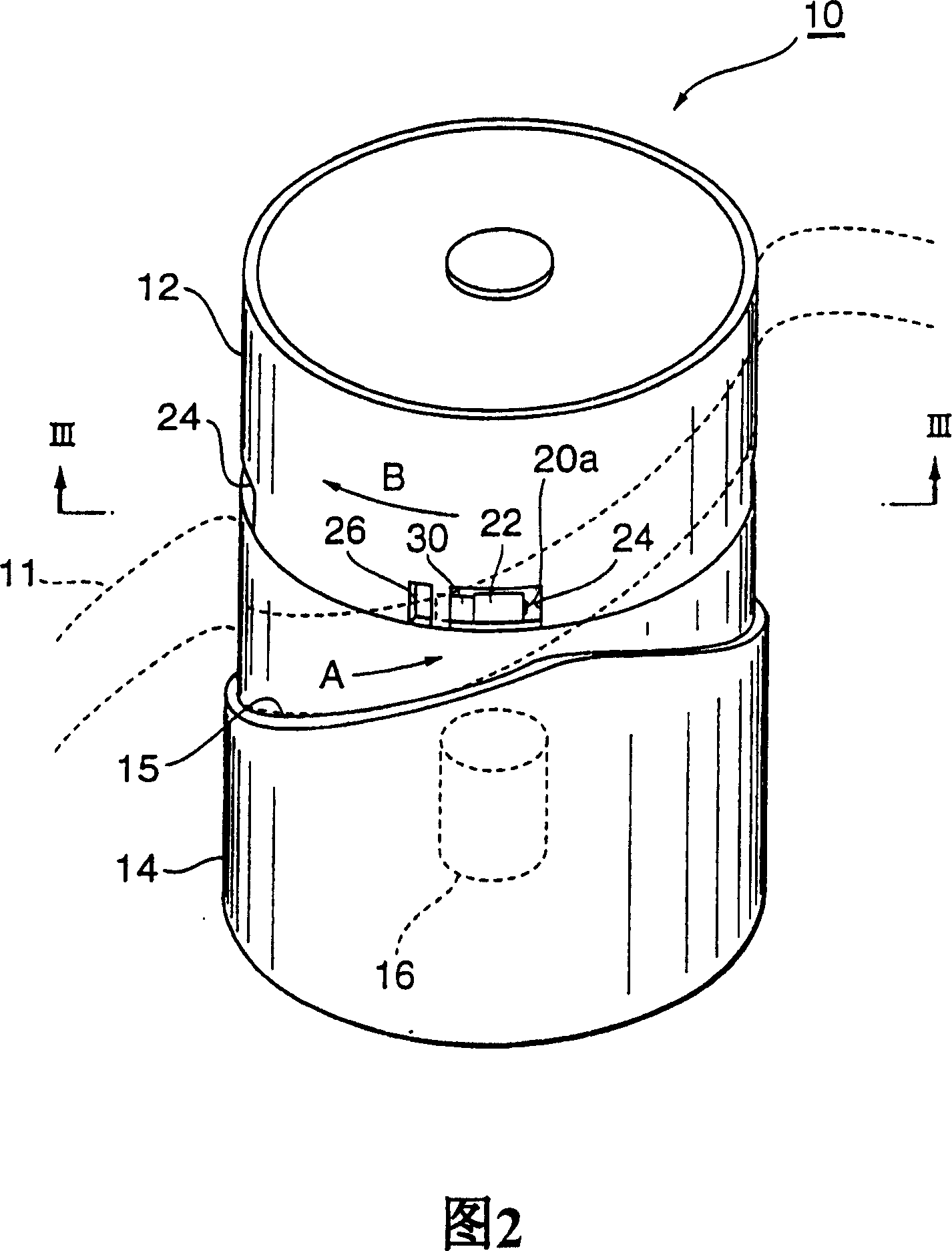
[0081] FIG. 7 is a perspective view of the rotary head 10 of this embodiment. In addition, FIG. 8 is a diagram of the rotating drum 12 viewed from the direction VIII-VIII in FIG. 7. The magnetic heads 20a to 20d are mounted on, for example, AlTiC (Al 2 O 3TiC) formed on the base 40 of approximately rectangular parallelepiped shape. The base 40 on which the magnetic heads 20 a to 20 d are mounted is fixed to a support member 41 arranged inside the rotating drum 12. The central part of the supporting member 41 is fixed to a shaft 42 erected on the bottom surface of the rotating drum 12. Therefore, the magnetic heads 20 a to 20 d themselves do not move to the inside or outside of the rotating drum 12.
[0082] On the base 40, a groove 40a is formed on the surf...
Embodiment approach 3
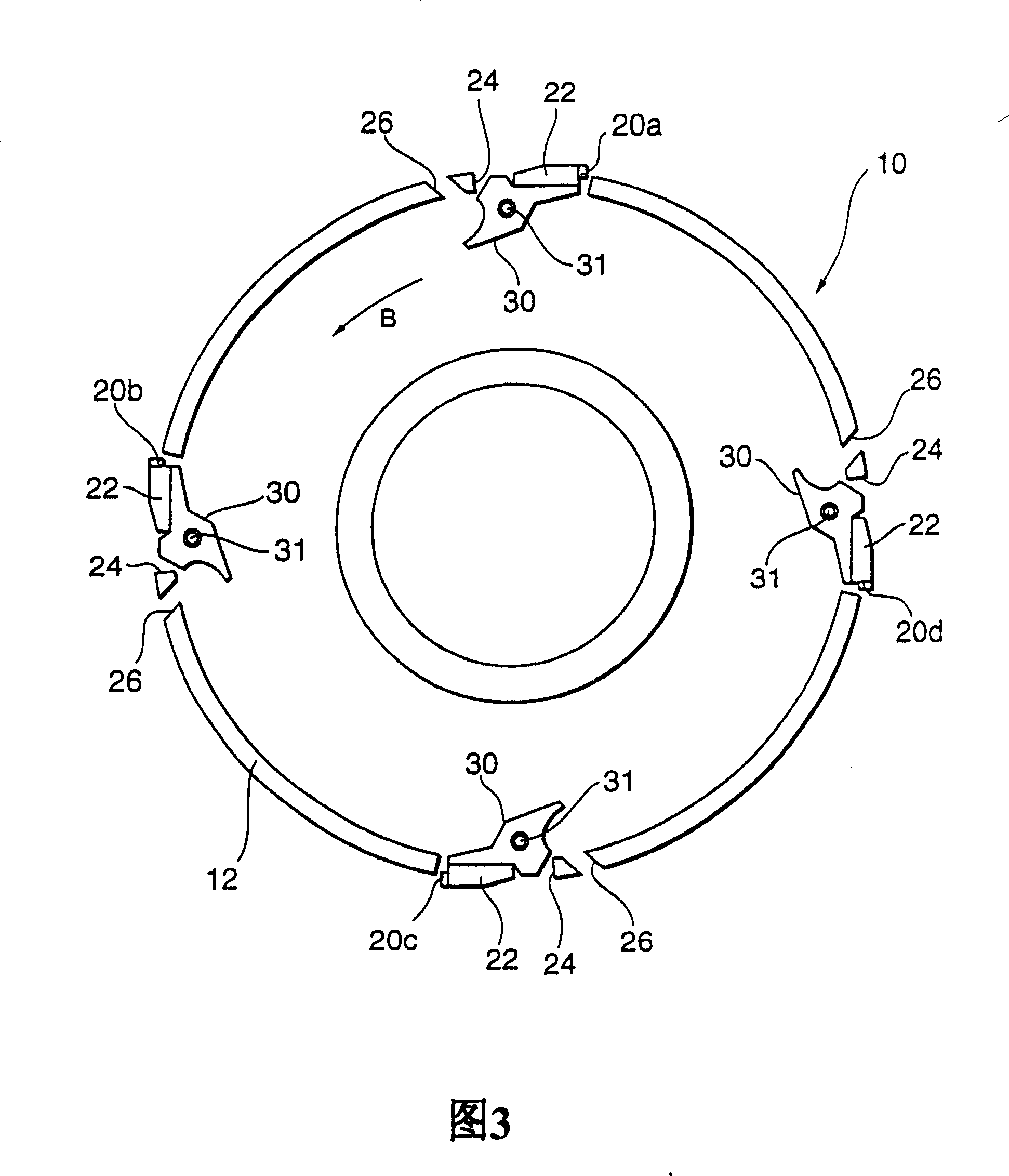
[0093] 14 is a perspective view of the rotary head 10 of this embodiment, FIG. 15 is a view of the rotary drum 12 viewed from the XV-XV direction of FIG. 14, and FIG. 16 is an enlarged view of the vicinity of a magnetic head 20a provided on the rotary head 10. On the rotary head 10, two inductive magnetic heads 20b, 20d and two magnetoresistance effect magnetic heads 20a, 20c dedicated to reproduction are alternately arranged in the circumferential direction, but the arrangement of the magnetic heads 20a-20d is not limited to this.
[0094] The base 22 on which the magnetic heads 20a to 20d are mounted is arranged inside the rotating drum 12, and is supported by a cantilever 30 made of stainless steel such as SUS304. The cantilever 30 is supported by a support stand 27 mounted on the inner peripheral surface of the rotating drum 12. The cantilever 30 has flexibility and supports the magnetic heads 20a to 20d in the direction of arrow F so as to swing. Specifically, the material se...
PUM
 Abstract
Description
Claims
Application Information