Valve for controlling a fluid

A fluid, throttle valve technology, applied in valve details, valve devices, valve operation/release devices, etc., to solve problems such as sticking on the valve body, tilting of the valve armature, material wear, etc.

Inactive Publication Date: 2008-01-30
ROBERT BOSCH GMBH
View PDF7 Cites 0 Cited by
  • Summary
  • Abstract
  • Description
  • Claims
  • Application Information

AI Technical Summary

Problems solved by technology

[0003] The known gas valves of the type described above have the problem that when using oil-free gas due to lack of lubrication, material wear occurs in the area of ​​the valve armature and valve seat, which can tilt the valve armature and thus become stuck on the valve body, resulting in impairment of the valve function. premature failure

Method used


Image

  • Valve for controlling a fluid
  • Valve for controlling a fluid
  • Valve for controlling a fluid

Examples


Embodiment Construction

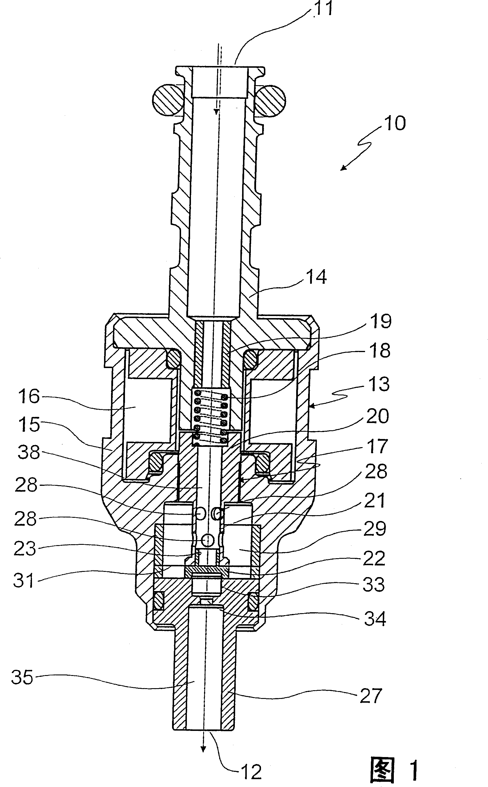
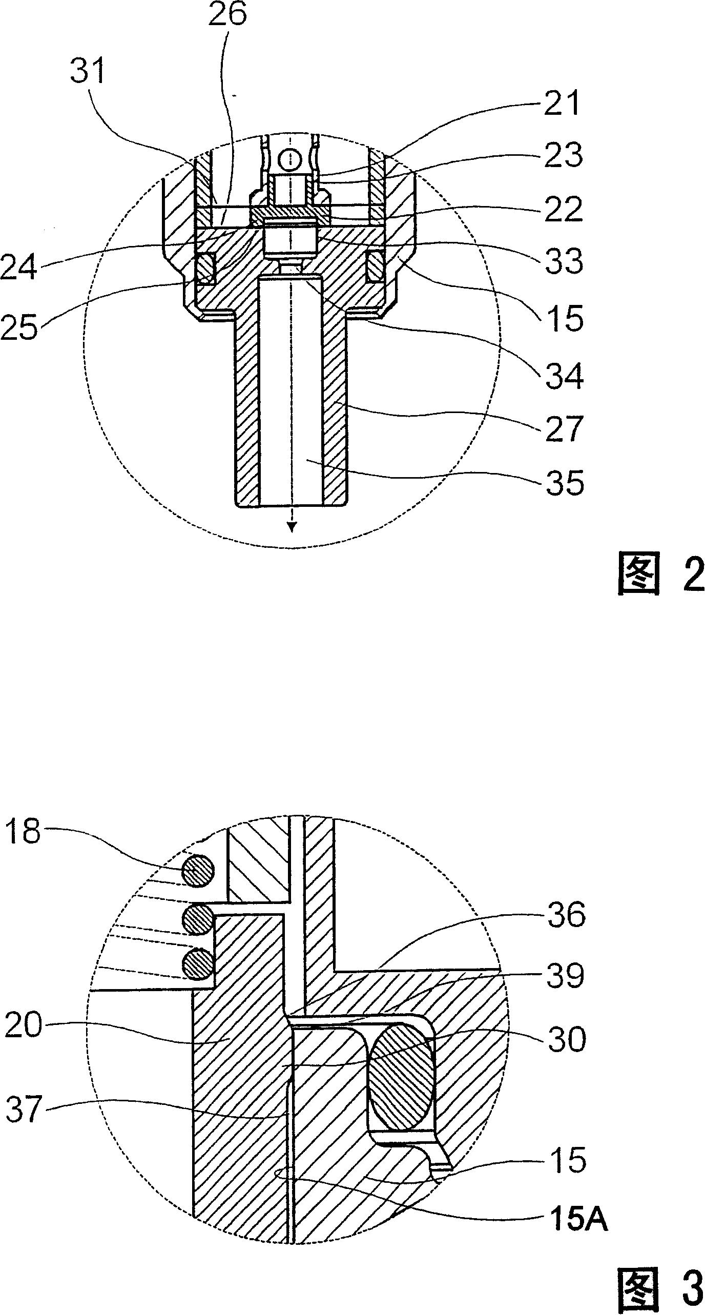
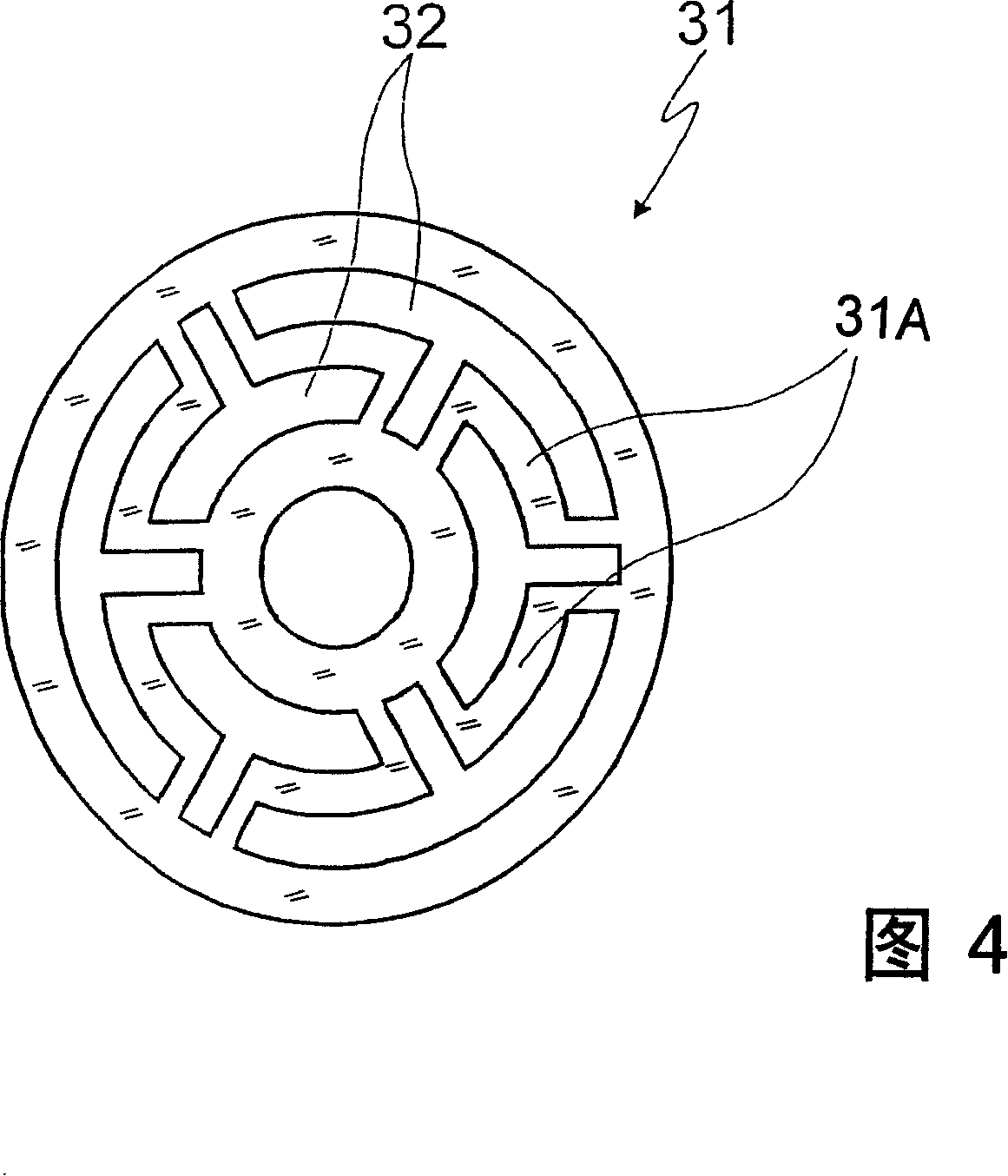
[0032] A gas valve 10 is shown in FIGS. 1-4 , which is designed for use in a fuel cell or a gas engine and serves to regulate the flow of hydrogen or natural gas from the inflow side 11 to the outflow side 12 .

[0033] The gas valve 10 comprises a multi-part housing 13 with a substantially tubular joint 14 forming the fluid inflow side 11 on the joint 14, which is passed through a flange-shaped flange with an outer diameter The flange of the enlargement is inserted axially into an essentially hollow-cylindrical central valve body 15 . A space 16 is formed in the central valve body 15 for the solenoid actuating unit, which interacts with a valve armature 17 which is supported via a helical spring 18 on a sleeve inserted into the bore of the connection 14 19 on.

[0034] The valve armature 17 comprises a large-diameter area 20 and a small-diameter area 21 formed in a constricted form, on the end face of the small-diameter area is connected a valve closing element 22, which is ...


PUM


Abstract

A valve for controlling a fluid, in particular for controlling a gas, is described, encompassing a valve housing an actuation unit for an at least locally tubular valve armature which is guided axially displaceably and is equipped with a valve closure member by which a fluid flow between an inflow side and an outlet side is controllable and which coacts with a valve seat. The valve armature comprises a guidance collar in a region remote from the valve closure member, and is equipped with a second guidance in a region offset with respect to the guidance collar.

Description

technical field [0001] The present invention relates to a fluid control valve, especially a gas control valve. Background technique [0002] Valves of this type are known in practice, for example as gas injection valves, for use in fast-ignition engines of vehicles powered by petroleum gas (NG=natural gas). Such valves, which are designed for gas actuation, comprise a valve housing, in which a valve armature is guided so as to be axially displaceable. The movement of the valve armature can be brought about by means of a solenoid actuating unit, and the valve armature is equipped with a valve closing element, which cooperates with the valve seat, by means of which the fluid flow between the inflow side and the outflow side of the valve can be controlled. [0003] The known gas valves of the type described above have the problem that when using oil-free gas due to lack of lubrication, material wear occurs in the area of ​​the valve armature and valve seat, which can tilt the ...

Claims


Application Information

Patent Timeline
Patent Type & Authority Patents(China)
IPC IPC(8): F16K31/06F02M21/02
CPCY02T10/32F02M21/0266F02M21/0281F16K31/0655F16K31/0651F02M21/0254Y02T10/30
Inventor 瓦尔德马尔·汉斯伊恩·费伊弗兰克·布伦纳弗兰克·米勒马丁·迈尔京特·班特莱昂坦-雄·源-舍费尔托马斯·海巴内尔凯·克勒格尔
Owner ROBERT BOSCH GMBH
Why Eureka
Try Eureka