Method and apparatus for measuring material piezoelectric coefficient by using scanning near-field microwave microscopy

A technology for scanning near-field and piezoelectric coefficients, which is used in measuring devices, measuring electrical variables, instruments, etc., and can solve the problems of unable to obtain piezoelectric coefficients, unable to obtain deformation data, and unable to directly measure piezoelectric deformation.

Inactive Publication Date: 2008-02-20
UNIV OF SCI & TECH OF CHINA
View PDF5 Cites 1 Cited by
  • Summary
  • Abstract
  • Description
  • Claims
  • Application Information

AI Technical Summary

Problems solved by technology

Although theoretically speaking, the deformation caused by the piezoelectric effect can be obtained by measuring the distance change of the sample probe through the above relationship, but in fact, the piezoelectric deformation is very small (sometimes less than 1 nanometer), so the weak signal caused by this deformation It will be overwhelmed by the inherent noise of the system, so that the deformation data cannot be obtained. That is to say, the existing scanning near-field microwave microscope cannot directly measure the piezoelectric deformation, and naturally the piezoelectric coefficient cannot be obtained.

Method used


Image

  • Method and apparatus for measuring material piezoelectric coefficient by using scanning near-field microwave microscopy
  • Method and apparatus for measuring material piezoelectric coefficient by using scanning near-field microwave microscopy
  • Method and apparatus for measuring material piezoelectric coefficient by using scanning near-field microwave microscopy

Examples


Embodiment 1

[0033] Embodiment 1: Measuring the longitudinal piezoelectric coefficient of PZT piezoelectric ceramics

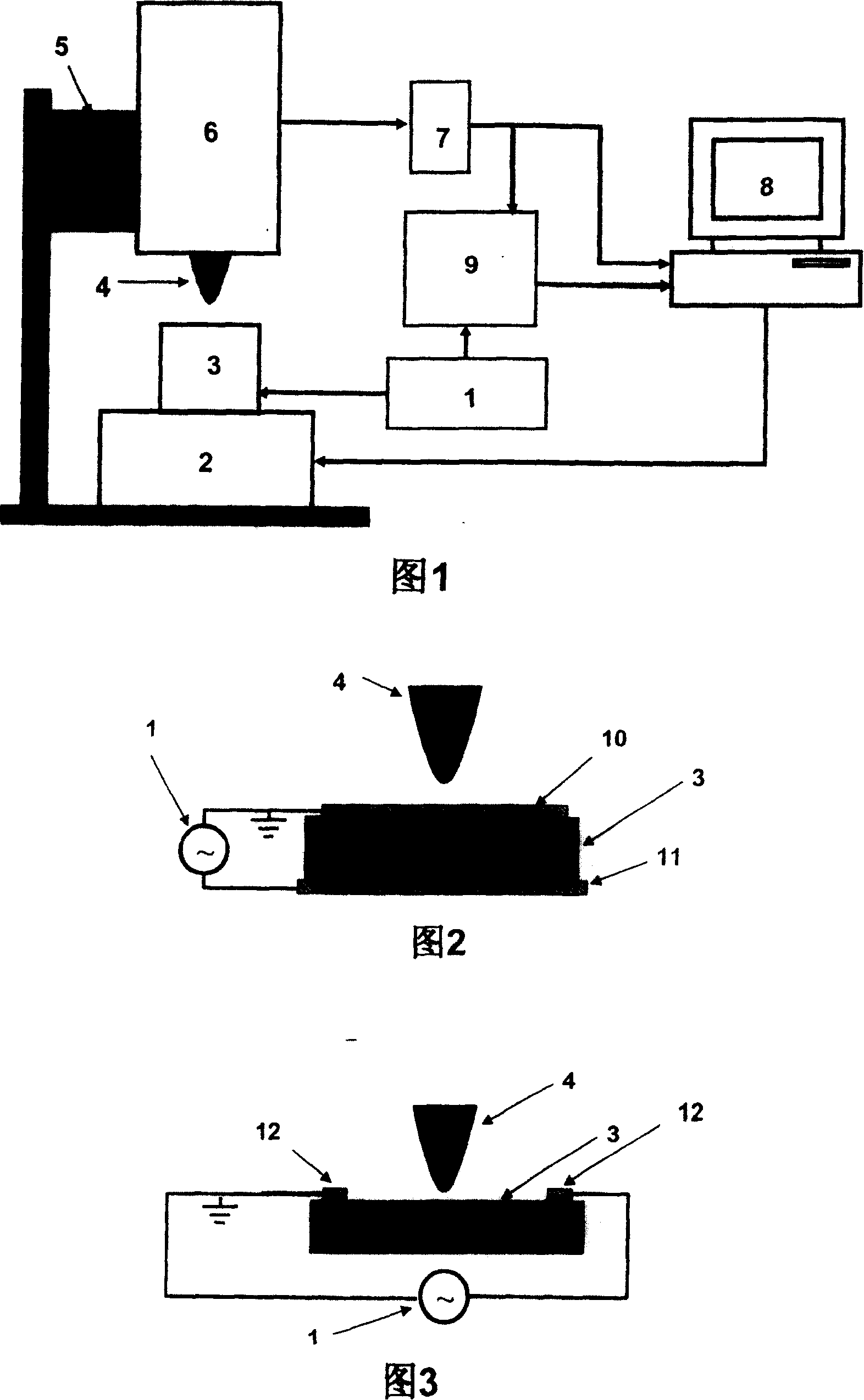
[0034] (1) As shown in Figure 2, in a 5mm×5mm×4mm lead zirconate titanate (Pb(ZrTi)O 3 , referred to as: PZT) electrodes are set on the upper and lower surfaces of the piezoelectric ceramic block sample, which is fixed on the scanning stage of a near-field microwave microscope (EMP2001, Ariel Technology, Inc., USA), and connected as shown in Figure 1 and Figure 2. Equipment and power supply: connect the sinusoidal alternating voltage generated by the signal generator (SG1643, Jiangsu Hongzerruite Electronic Equipment Co., Ltd.) to the two electrodes of the piezoelectric ceramic sample, and connect the signal output by the near-field microwave microscope to the lock Phase amplifier (SR 830, U.S. Stanford Research Systems, Inc.) input terminal, the modulated signal that the signal generator produces separates one and is connected with the lock-in amplifier reference signal i...

Embodiment 2

[0040] Embodiment 2: measure the longitudinal piezoelectric coefficient of PZT film

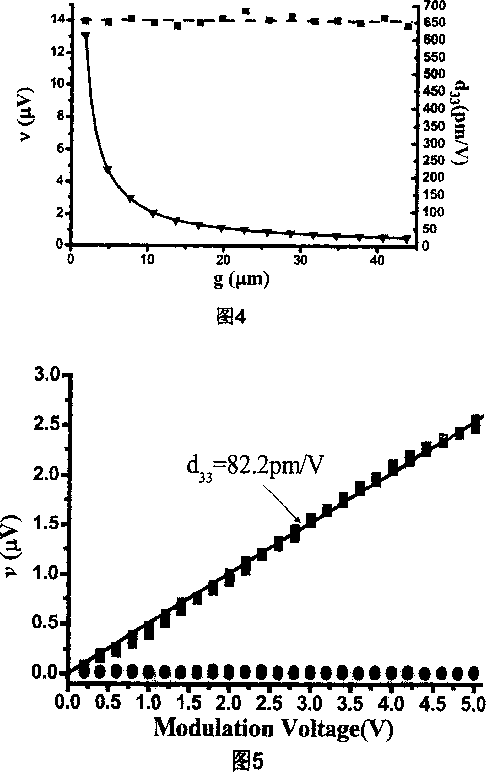
[0041] The sample is a PZT piezoelectric film with a thickness of 1 μm. Electrodes are fabricated on the sample as shown in FIG. 2 . The near-field microwave microscope, signal generator, and lock-in amplifier selected are the same as in Example 1, and the circuit connection method is also the same. In the near-field microwave microscope, the distance between the probe and the electrode on the sample is selected as 1.24 microns, and remains unchanged. The calibration constant A of the scanning near-field microwave microscope, the frequency response coefficient S of the microwave system of the scanning near-field microwave microscope, and the resonant frequency f of the microwave resonant cavity when there is no sample 0 All the same as in Example 1. Figure 5 shows the change of the output of the lock-in amplifier with the modulation voltage (square symbols, the modulation frequency is fixed ...


PUM


Abstract

The invention relates to a method and a device for testing piezoelectric coefficient with near field electron scanning microscope according to converse piezoelectric effect. The invention comprises: making sample for testing and measuring the dielectric constant epsilon, setting distance between the microscope probes and sample and then: (1) connecting the output terminal of the signal generator with the sample electrode, and separating one terminal to connect with the reference signal input terminal of phase-locking amplifier to adding cycle modulation signal on the sample electrode; (2) connecting the input of the phase-locking amplifier with the frequency signal output terminal of the microscope controller, and the output terminal being connected to the data collection and process system, a cycle modulation signal v in the microscope signal being made by cyclomorphosis of piezoelectricity on probe sample; (3) calculating piezoelectric coefficient according to formula dij=-1 / (5.80b2-9.09b+3.77).gL / ASf0l.nu / V.

Description

technical field [0001] The invention relates to a measurement technology for piezoelectric properties of materials, in particular to a method and a device for measuring piezoelectric coefficients of materials by utilizing inverse piezoelectric effects. Background technique [0002] Piezoelectric effect refers to the phenomenon that materials generate electric charges under the action of external pressure (called positive piezoelectric effect) or produce mechanical deformation under the action of external voltage (called inverse piezoelectric effect). Manifestations. Materials with pronounced piezoelectric effect are called piezoelectric materials. The charge generated by a piezoelectric material under the action of unit pressure or the amount of deformation generated under the action of unit voltage is called the piezoelectric coefficient, which is used to measure the magnitude of the piezoelectric effect. Due to the realization of electromechanical coupling, piezoelectric...

Claims


Application Information

Patent Timeline
Patent Type & Authority Patents(China)
IPC IPC(8): G01R29/22
Inventor 高琛赵振利刘磁辉
Owner UNIV OF SCI & TECH OF CHINA
Why Eureka
Try Eureka