Cycular-flowing type fluid pump

A liquid pump, flow-type technology, applied in the field of circumferential flow liquid pumps, can solve problems such as unreliable avoidance of air locks, lengthening of side walls, etc.

Inactive Publication Date: 2008-03-05
MITSUBISHI ELECTRIC CORP
View PDF2 Cites 0 Cited by
  • Summary
  • Abstract
  • Description
  • Claims
  • Application Information

AI Technical Summary

Problems solved by technology

However, since the cross section of the through hole 12 is circular and the cross section of the air release channel 11 is flat, there is a problem that the side wall of the air release channel 11 that communicates the pump flow path 7 with the through hole 12 be

Method used


Image

  • Cycular-flowing type fluid pump
  • Cycular-flowing type fluid pump
  • Cycular-flowing type fluid pump

Examples


Embodiment Construction

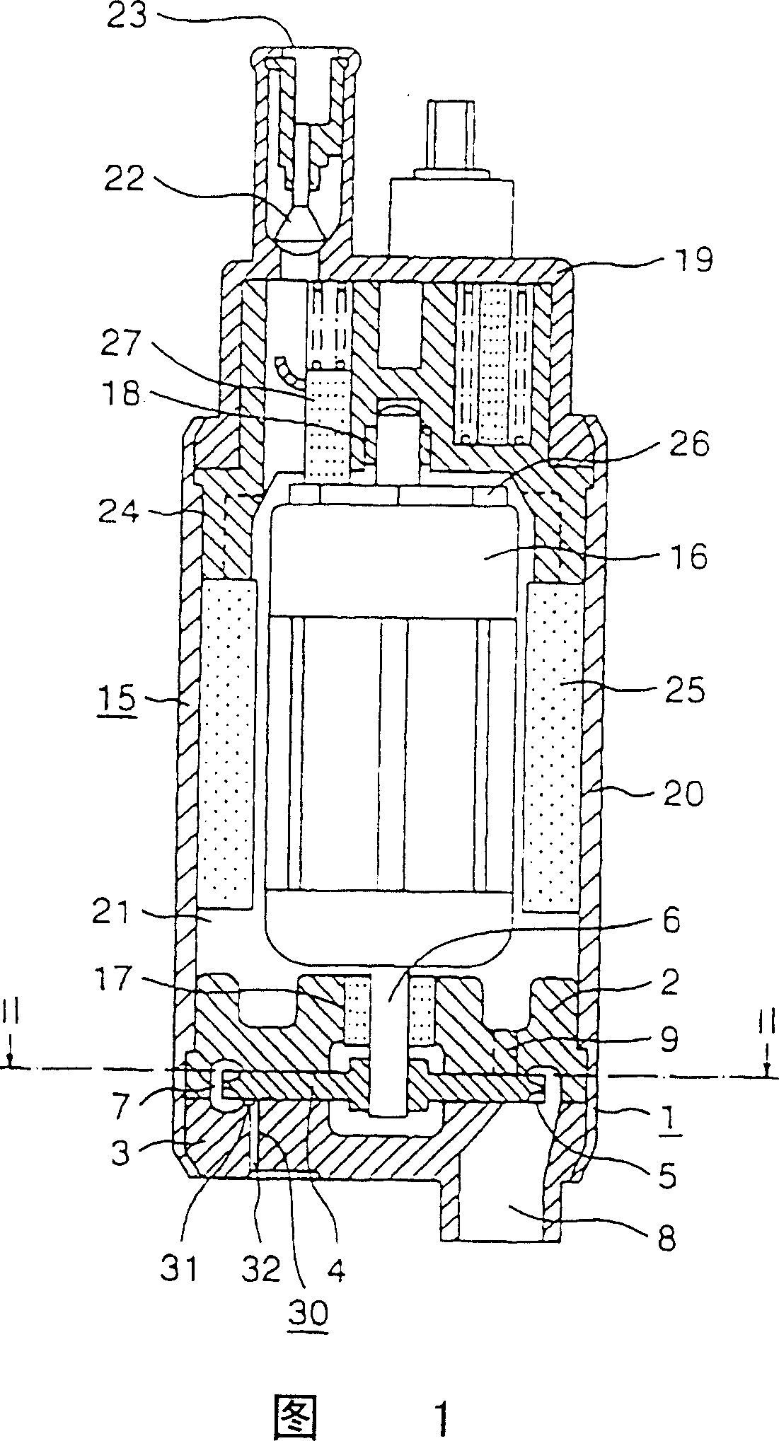
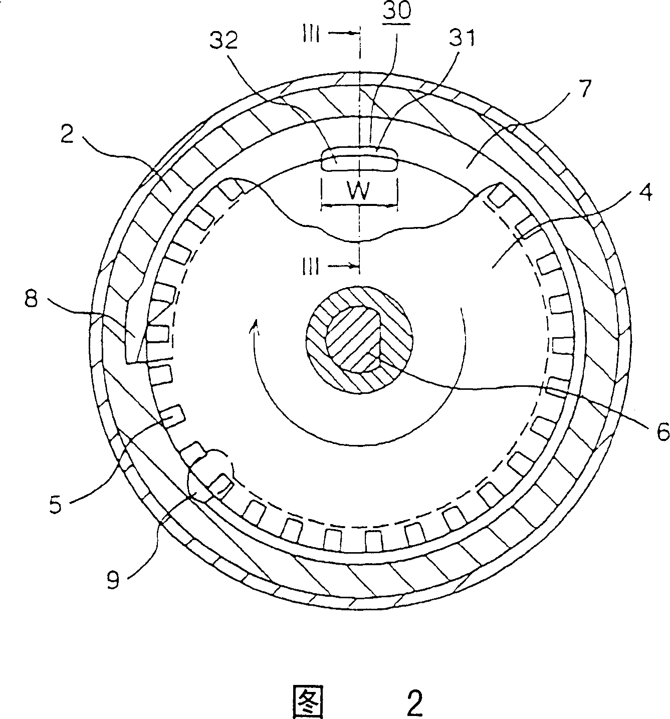
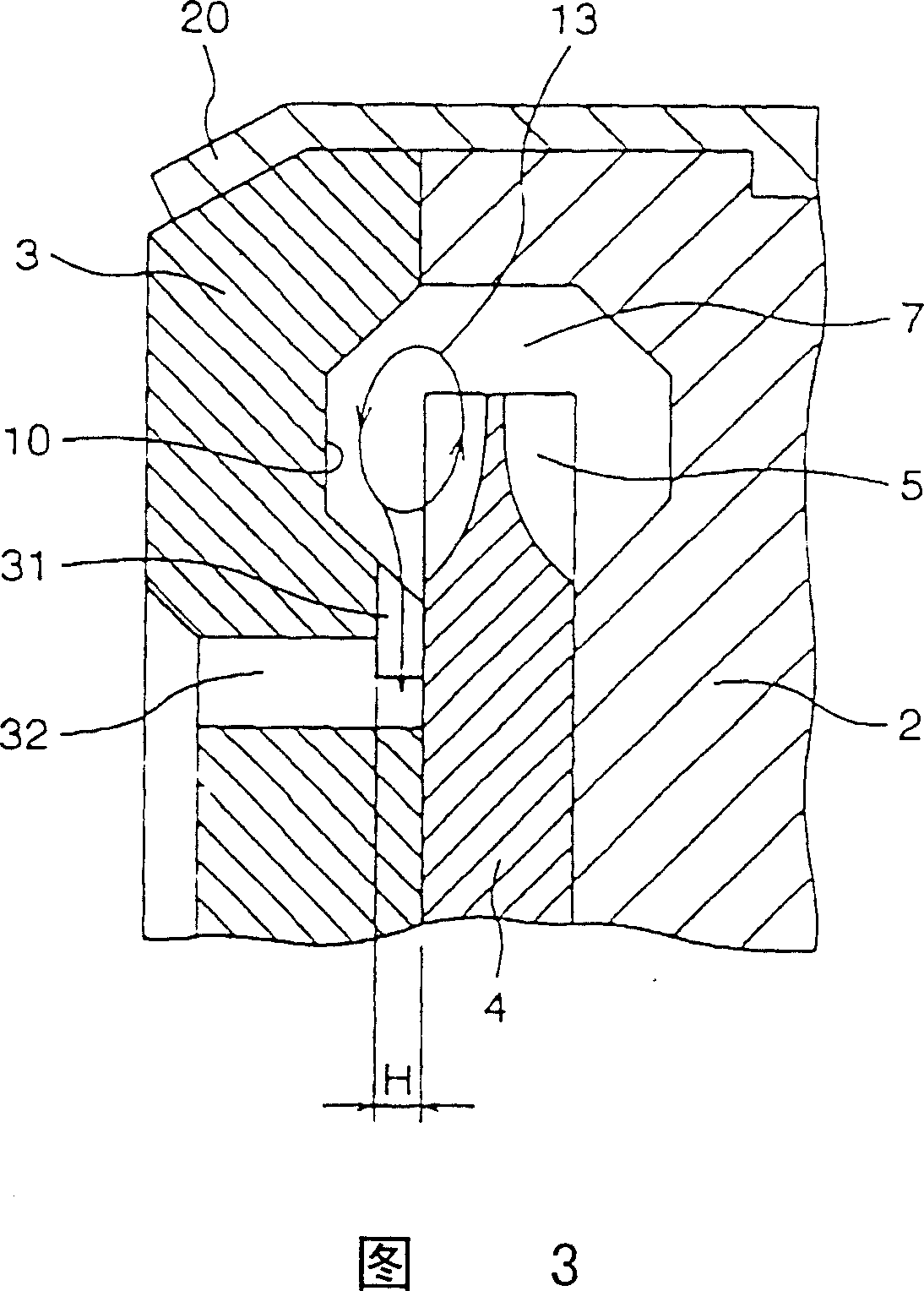
[0026] 1 is a longitudinal cross-sectional view of a circular flow type liquid pump according to an embodiment of the present invention, FIG. 2 is an enlarged cross-sectional view taken along line II-II in FIG. 1 , and FIG. 3 is an enlarged cross-sectional view taken along line III-III in FIG. 2 . In the figure, 1 to 10, 13, 15 to 27 have the same structure as the above-mentioned conventional device, and the description thereof is omitted.

[0027] In the drawing, on the cover 3 of the pump casing assembly 1, as shown in FIG. 3, the air release passage 31 is provided near the impeller 4 in the inner peripheral portion of the pump flow path 7, and the air release passage 31 is different in height. It opens at the position of the bottom surface portion 10 of the pump flow path 7 (a position located on the inner side in the circumferential direction of the bottom surface portion 10 from the bottom surface portion 10 and close to the impeller 4 ) and extends in the radial direction...


PUM


Abstract

A circumferential flow type liquid pump wherein a degassing passage opened in a stepped portion-carrying state in a bottom wall portion and extending radially inward is formed in the vicinity of an impeller in an inner circumferential portion of a pump flow passage, to allow communication between this degassing passage and the exterior of a pump casing assembly (1), and a cross-sectionally arcuate through port which has a cross-sectional area sufficiently larger than that of the degassing passage and which extends along the pump flow passage is provided. The through port may comprise plurality of through ports arranged in the range of the cross-sectionally arcuate area, or a through port directly communicating with the pump flow passage without the degassing passage interposed therebetween.

Description

technical field [0001] The present invention relates to a circular flow type liquid pump, and more particularly, to a circular flow type liquid pump serving as a fuel pump for sucking liquid fuel such as gasoline from a fuel tank in a vehicle internal combustion engine. Background technique [0002] 7 is a longitudinal cross-sectional view showing a conventional circular flow type liquid pump disclosed in, for example, Japanese Patent Publication No. 3239 of 1995, FIG. 8 is an enlarged cross-sectional view taken along line VIII-VIII in FIG. 7 , and FIG. Enlarged sectional view of line IX-IX in the middle. [0003] In the drawing, reference numeral 1 denotes an assembly of a pump casing, and the assembly is composed of a pump casing body 2 and a cover 3 . An impeller 4 having a blade portion 5 on an outer peripheral edge is provided in the pump casing assembly 1 . The impeller 4 is supported by a center shaft 6 and is rotatable relative to the pump casing assembly 1 about it...

Claims


Application Information

Patent Timeline
IPC IPC(8): F04D5/00F04D29/44F04D9/00
CPCF04D9/002F04D5/002
Inventor 吉冈浩
Owner MITSUBISHI ELECTRIC CORP
Why Eureka
Try Eureka