
Slurry flotation system additionally provided with buffer device

A buffer device and pulp technology, applied in flotation, solid separation and other directions, can solve the problem of easy occurrence of air resistance, large fluctuation of the amount of clean coal and flotation agent mixed into the flotation machine, and large interference of pulp flotation effect, etc. problem, to achieve the effect of reducing volatility, suitable for promotion, and convenient and simple transformation process

Inactive Publication Date: 2017-09-15
黑龙江宝泰隆新能源新材料研究院
View PDF0 Cites 0 Cited by
  • Summary
  • Abstract
  • Description
  • Claims
  • Application Information

AI Technical Summary

Problems solved by technology

[0003] The present invention aims to solve the problem that air resistance is prone to occur during the feeding process due to uneven mixing of clean coal and flotation agent from the slurry preparation device and large fluctuations in the amount of material entering the flotation machine. In addition, a large number of manual operations The problem of large interference with the flotation effect of the pulp, and then provides a pulp flotation system with a buffer device

Method used


Image

  • Slurry flotation system additionally provided with buffer device
  • Slurry flotation system additionally provided with buffer device

Examples


Embodiment 1

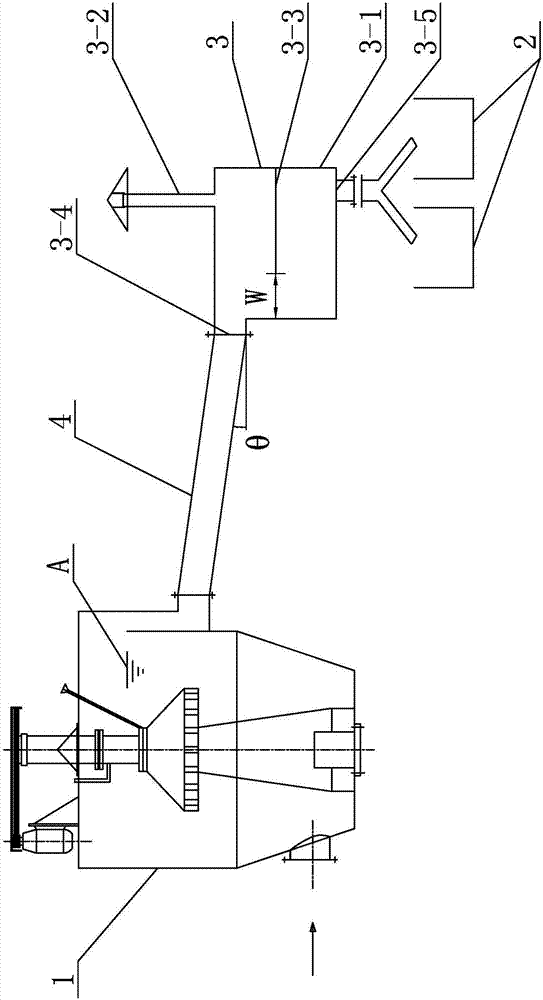
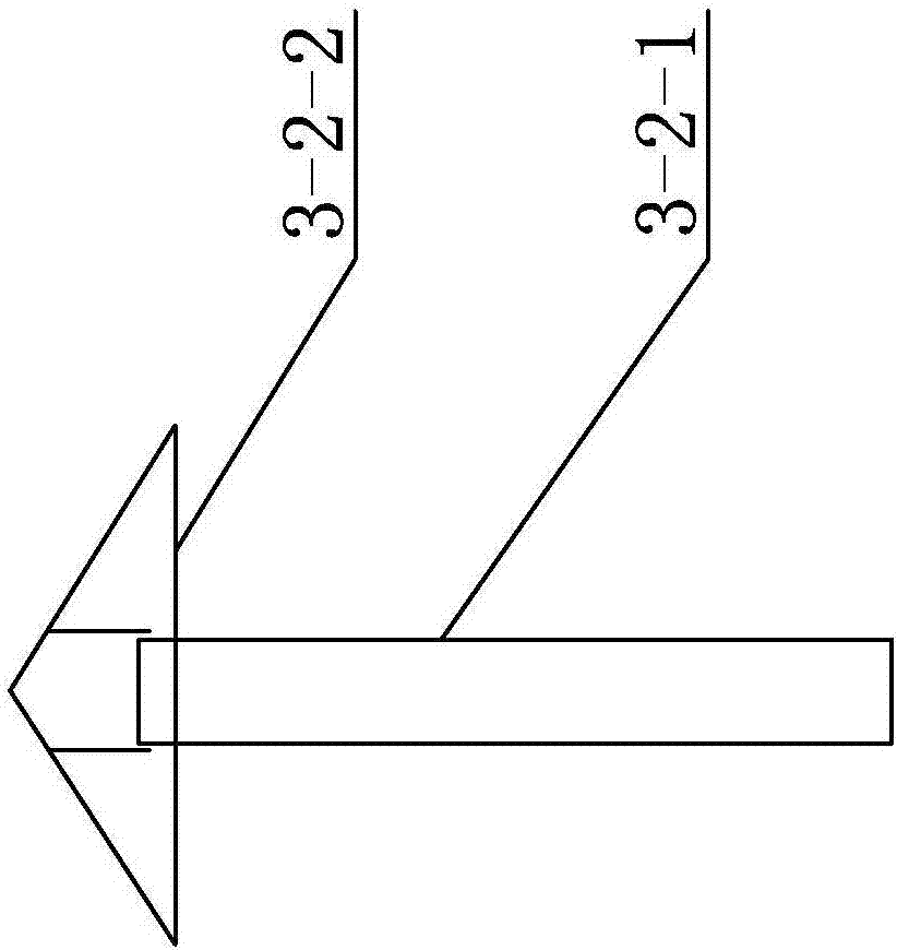
[0013] Example 1: Combining Figure 1 to Figure 2 Illustrate present embodiment, present embodiment comprises pulp preparer 1 and flotation device 2, and the outlet end of described pulp preparer 1 is arranged near the inlet end of flotation device 2, and it also comprises buffer device 3, and buffer device 3 comprises container 3-1. Exhaust device 3-2 and baffle plate 3-3. The container 3-1 is arranged between the pulp preparer 1 and the flotation device 2. The container 3-1 is processed with the pulp preparer 1 The feed port 3-4 connected to the outlet end of the container 3-1 is also processed with a discharge port 3-5 connected to the inlet end of the flotation device 2, and the outer wall of the container 3-1 is provided with The exhaust device 3-2, the exhaust device 3-2 communicates with the inner cavity of the container 3-1, the inner cavity of the container 3-1 is provided with a baffle 3-3, and the surface of the baffle 3-3 faces the container 3-1 feed port 3-4 sett...

Embodiment 2

[0017] Embodiment 2: Combination figure 1 Describe this embodiment, in this embodiment, the baffle 3-3 is a straight plate, and the baffle 3-3 is arranged horizontally, and one end of the baffle 3-3 is fixedly connected with the side inner wall of the container 3-1, and the baffle The other end of 3-3 is provided with a gap with the inner wall of the other side of container 3-1.

Embodiment 3

[0018] Example Three: Combining figure 1 To illustrate this embodiment, in this embodiment, the gap between the baffle plate 3-3 and the inner wall of the container 3-1 is a material channel, the width of the material channel is W, and the value of W ranges from 30 to 60 cm. Within this width range, the ore pulp can be guaranteed to flow down smoothly, and the next step of flotation processing can be realized smoothly.


PUM


Abstract

The utility model relates to an ore pulp flotation system equipped with a buffer device, which relates to an ore pulp flotation system. Due to the uneven mixing of clean coal and flotation agent from the slurry preparation device and large fluctuations in the amount of material entering the flotation machine, air resistance is prone to occur during the feeding process. In addition, a large number of manual operations affect the flotation of the slurry. The effect is very disturbing. In this product, the container is set between the pulp preparer and the flotation device, and the container is processed with a feed port connected with the outlet end of the pulp preparer, and the container is also processed with an inlet port connected with the flotation device Connected to the discharge port, the outer wall of the container is provided with an exhaust device, the exhaust device is connected to the inner cavity of the container, the inner cavity of the container is provided with a baffle, and the surface of the baffle is set towards the feeding port of the container . This product is used for recovery of clean coal.

Description

technical field [0001] The invention relates to a pulp flotation system, which belongs to the technical field of mining. Background technique [0002] Mining refers to the extraction of naturally occurring minerals such as coal, minerals, crude oil or natural gas. This category includes underground or above-ground mining, the operation of mines, and generally all ancillary work performed on or near mine sites aimed at processing raw materials, such as grinding, beneficiation, and processing. Also included are the preparations required to make the raw material available for sale. However, it does not include water storage, purification and distribution, as well as geological exploration and construction engineering activities. The equipment involved in the mining process is diverse, and problems have become increasingly prominent in the actual use process. For example, in the process of using the slurry preparer and flotation device to extract clean coal from the slurry, du...

Claims


Application Information

Patent Timeline
Patent Type & Authority Applications(China)
IPC IPC(8): B03D1/14
CPCB03D1/14
Inventor 宫振宇马世海
Owner 黑龙江宝泰隆新能源新材料研究院
Learn More