Continuously variable transmission

A technology of a continuously variable transmission device and a transmission mechanism, which is applied in the direction of control devices, transmission devices, transmission device control, etc., and can solve problems such as the deterioration of the alignment accuracy of the input shaft 107, the limitation of the alignment accuracy of the input shaft 107, and the accuracy error of parts, etc. To achieve the effect of suppressing the occurrence of abnormal sound, improving meshing accuracy and centering accuracy

Inactive Publication Date: 2008-03-26
MITSUBISHI MOTORS CORP
View PDF4 Cites 0 Cited by
  • Summary
  • Abstract
  • Description
  • Claims
  • Application Information

AI Technical Summary

Problems solved by technology

However, because the bearing supporting one end (the right end in the figure) of the input shaft 107 and the bearing 106 supporting one end (the right end in the figure) of the primary shaft 103 are provided on the bearing 27 between the primary shaft 103 and the input shaft 107, there is a certain Parts accuracy errors or assembly errors are included within the allowable range, so the center lines of these shafts are inconsistent, and there is a problem that the centering accuracy of the input shaft 107 deteriorates.
In addition, it is difficult to make the centerlines of these bearings coincide with each other with high precision in normal assembly work, and there has always been a certain limit on the improvement of the centering accuracy of the input shaft 107.

Method used


Image

  • Continuously variable transmission
  • Continuously variable transmission
  • Continuously variable transmission

Examples


Embodiment Construction

[0050] Next, an embodiment in which the present invention is embodied as a belt-type continuously variable transmission for an FF (front-engine, front-wheel drive) vehicle will be described.

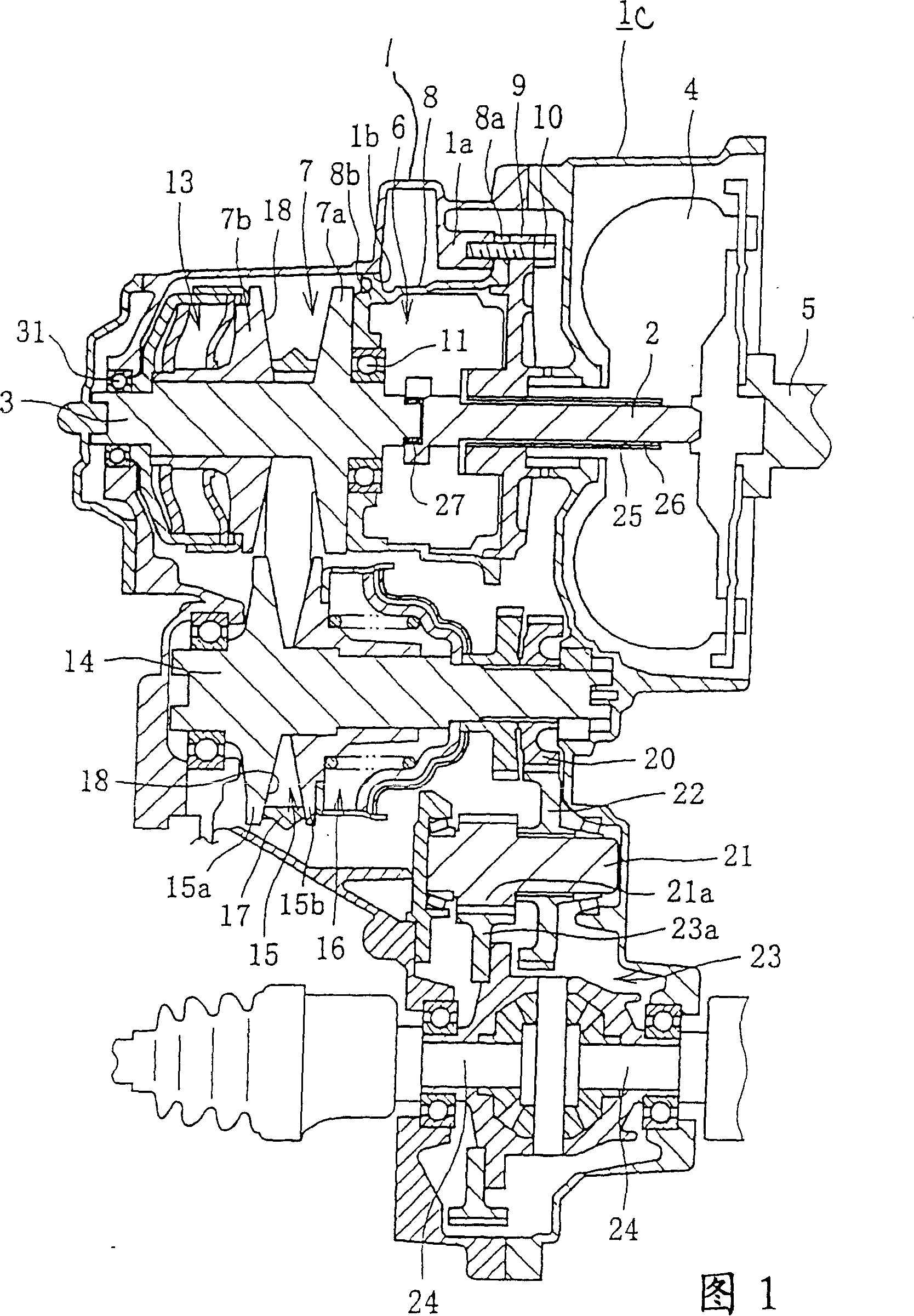
[0051] Fig. 1 shows the cross-section of a belt-type continuously variable transmission. This continuously variable transmission is connected to a torque converter 4 on the input side (right side in the figure), and a known pump wheel not shown is connected to a crankshaft 5 of an engine.

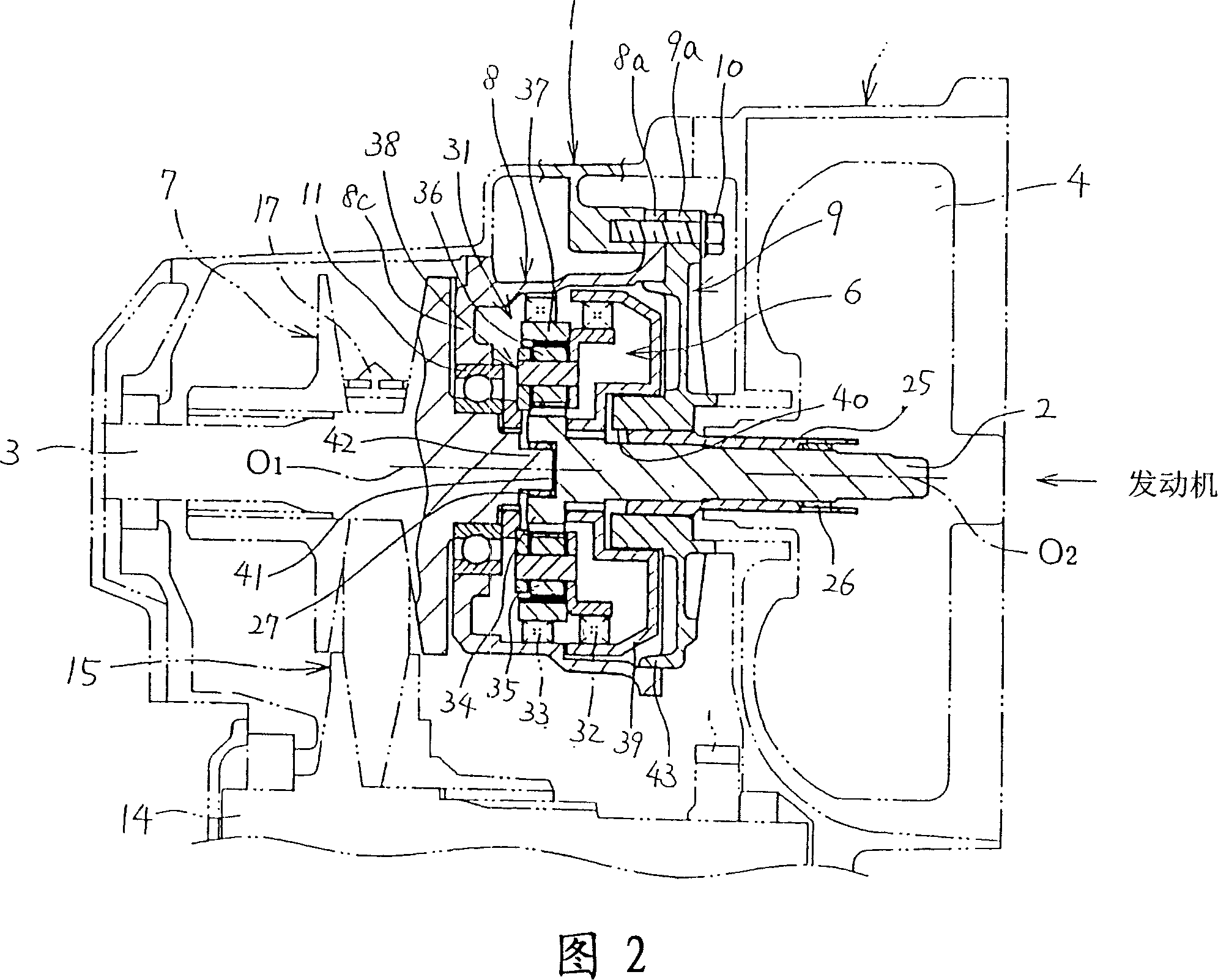
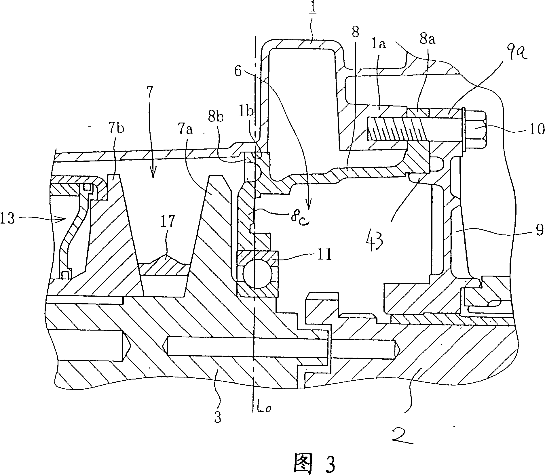
[0052] In the casing 1 of the continuously variable transmission device, the above-mentioned torque converter 4 is accommodated, and one end (the right end in the figure) is spline-connected to the input shaft (rotary shaft) 2 of the turbine, which is not shown in the torque converter 4, and connected to At the other end of the input shaft 2 (the left end in the figure), the forward and reverse switching mechanism 6 as a power disconnection mechanism described below is connected to the output part of t...


PUM


Abstract

A forward-speed / reverse-speed changeover mechanism 6, serving as a motive-force connection / disconnection mechanism, is accommodated into a housing member 8 fixed to a casing 1. To the forward-speed / reverse-speed changeover mechanism 6 an input end of a primary shaft 3 is connected. The housing member 8 rotatably supports the primary shaft 3 via a bearing member 11. On an imaginary line intersecting the primary shaft 3 perpendicularly and passing through the bearing member 11, a load-receiving element 1b, 8b is provided between the housing member 8 and the casing 1. The tension of a belt 17 is received by the load-receiving element 1b, 8b. As a result, it is possible to provide a bearing structure of a continuously variable transmission enabling holding the bearing members of the primary and secondary shafts at their regular positions against the tension of the belt and maintaining an optimum belt-alignment, thereby enhancing the durability of the continuously variable transmission.

Description

[0001] This application is a divisional application of the application whose filing date is September 8, 2000, the application number is 00124482.5, and the title of the invention is "continuously variable transmission device". technical field [0002] The present invention relates to a continuously variable transmission equipped with a forward and reverse switching mechanism. Background technique [0003] As a technique related to such a continuously variable transmission, for example, a belt-type continuously variable transmission described in Japanese Patent Application Laid-Open No. 10-274319 can be mentioned. In the transmission mechanism of this continuously variable transmission device, the primary shaft and the secondary shaft are arranged in parallel in the casing, and an endless belt is connected between the primary pulley provided on the primary shaft and the secondary pulley provided on the secondary shaft. constitute. The primary pulley and the secondary pulley...

Claims


Application Information

Patent Timeline
Patent Type & Authority Patents(China)
IPC IPC(8): F16H57/02B60K17/06F16H9/16F16H37/02F16H61/662
CPCF16H37/022F16H61/662F16H9/16
Inventor 殿畑厚泽山稔生岛嘉大
Owner MITSUBISHI MOTORS CORP
Why Eureka
Try Eureka