
Hand-held non-contact tonometer

A tonometer, non-contact technology, applied in the field of hand-held non-contact tonometer, can solve the problems of complex and expensive production of non-contact tonometer

Inactive Publication Date: 2008-04-09
REICHERT
View PDF6 Cites 3 Cited by
  • Summary
  • Abstract
  • Description
  • Claims
  • Application Information

AI Technical Summary

Problems solved by technology

The non-contact tonometer described in US Patent No. 4724843 is complex and expensive to produce

Method used


Image

  • Hand-held non-contact tonometer
  • Hand-held non-contact tonometer
  • Hand-held non-contact tonometer

Examples


Embodiment Construction

[0030] general structure

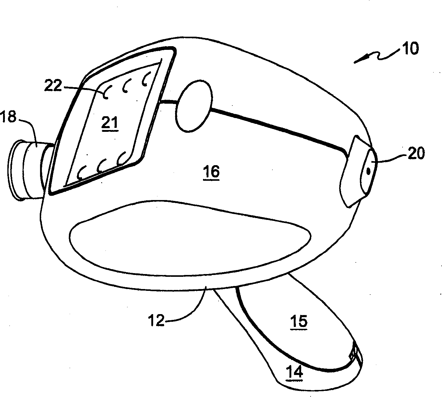
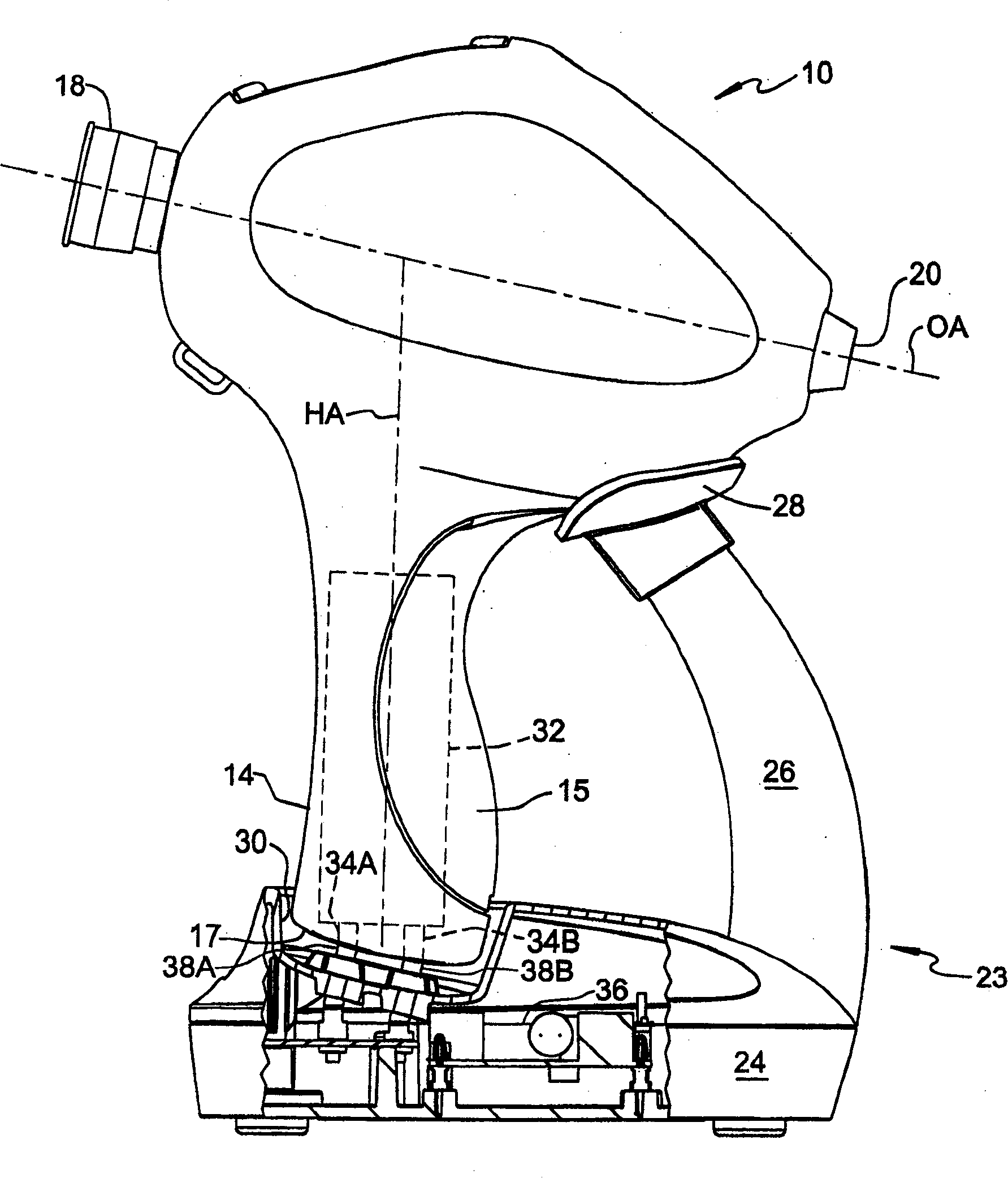
[0031] figure 1 Shown is a hand-held non-contact tonometer 10 formed in accordance with a preferred embodiment of the present invention. The tonometer 10 includes a housing 12 featuring an elongated handle portion 14 , and an upper head portion 16 connected to the top end of the handle portion 14 . Housing 12 is formed of two generally symmetrical halves joined along a vertical plane. The handle portion 14 includes an ergonomically designed grip 15 . As will be described in more detail below, the head portion 16 contains the tonometry system and the handle portion 14 contains the power supply for the tonometry system. Such as figure 1 Also visible are the operator's eyepiece 18 at one end of the head portion 16, the patient-facing front window 20 at the opposite end of the head portion, and the button with button tilted toward the operator near the operator's eyepiece 18. LCD display 21 of control overlay 22 .

[0032] figure 2 The tonometer ...


PUM


Abstract

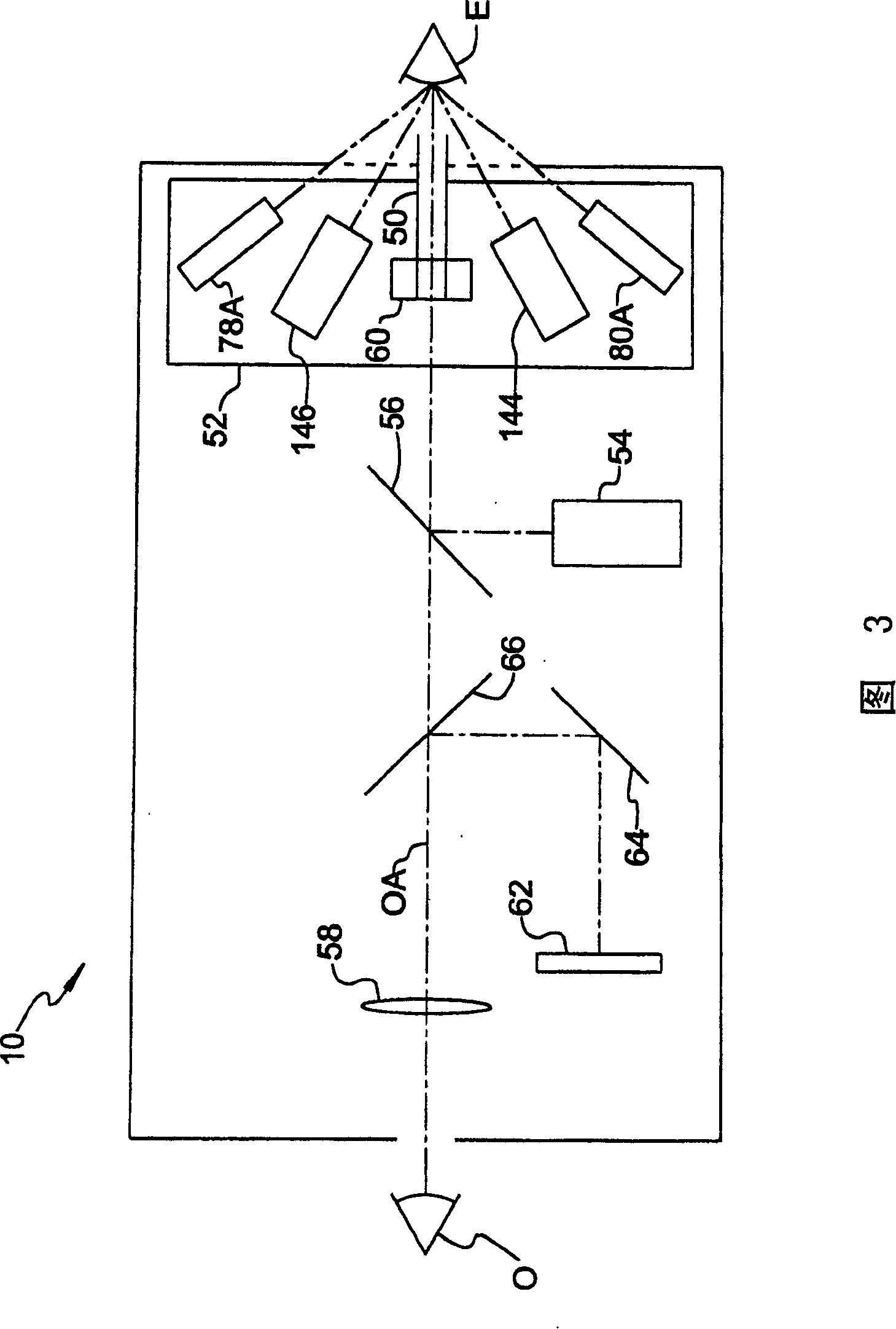
A hand-held non-contact tonometer (10) comprises a housing (12) having a handle portion (14) for enclosing a rechargeable D.C. power source (32) and an upper head portion (16) for enclosing alignment and tonometric measurement systems of the tonometer. An operator can directly view the patient's eye along an optical axis (OA) extending through the head portion of the housing, and an instructional display image is superimposed with the directly viewed image of the eye to guide the operator in X-Y-Z alignment based on data supplied by an afocal position detection system. A transceiver for wireless data exchange and a recharging support stand (23) are also provided.

Description

technical field [0001] The present invention relates generally to ophthalmic instruments, and more particularly, to a portable, hand-held, non-contact tonometer for measuring intraocular pressure in a patient's eye. Background technique [0002] Non-contact tonometers are widely used diagnostic instruments by ophthalmologists and medical professionals to measure the internal fluid pressure (intraocular pressure or IOP) in the eye and are often used to screen patients for elevated IOP associated with glaucoma. Non-contact tonometers typically operate by directing a pulse of fluid at the eye and observing deformation of the cornea. In conventional devices of the prior art, a fluid pump with a solenoid-driven piston compresses fluid in a pressurized chamber, and a fluid launch tube in communication with the pressurized chamber and aligned with the patient's eye delivers pulses of fluid to the eye so that The cornea deforms from its normal convex state to a concave state throug...

Claims


Application Information

Patent Timeline
IPC IPC(8): A61B3/16A61B3/10A61B3/15
CPCA61B3/165A61B3/152A61B2560/0456A61B3/0091A61B3/0058A61B3/16
Inventor C·J·佩尔茨瓦尔D·H·霍弗D·A·卢斯
Owner REICHERT
Learn More