Needle blade roll for quasi-cotton producing device

A technology for manufacturing a device and a needle roller, which is applied in the field of needle rollers, can solve the problems of short fibers 102, short fibers 102 are not easily entangled, etc., and achieves the effects of uniform micronization and improved strength

Inactive Publication Date: 2008-04-16
DAIKIN IND LTD
View PDF5 Cites 0 Cited by
  • Summary
  • Abstract
  • Description
  • Claims
  • Application Information

AI Technical Summary

Problems solved by technology

[0006] But, if use the existing needle roll 106 that constitutes like this, utilize the staple fiber 102 that fiber material 101 forms to become too short easily.
Therefore, when a plurality of short fibers 102 are gathered on the upper surface of the mesh conveyor belt 103, etc., the short fibers 102 may not be easily entangled with each other.

Method used


Image

  • Needle blade roll for quasi-cotton producing device
  • Needle blade roll for quasi-cotton producing device
  • Needle blade roll for quasi-cotton producing device

Examples


Deformed example 1

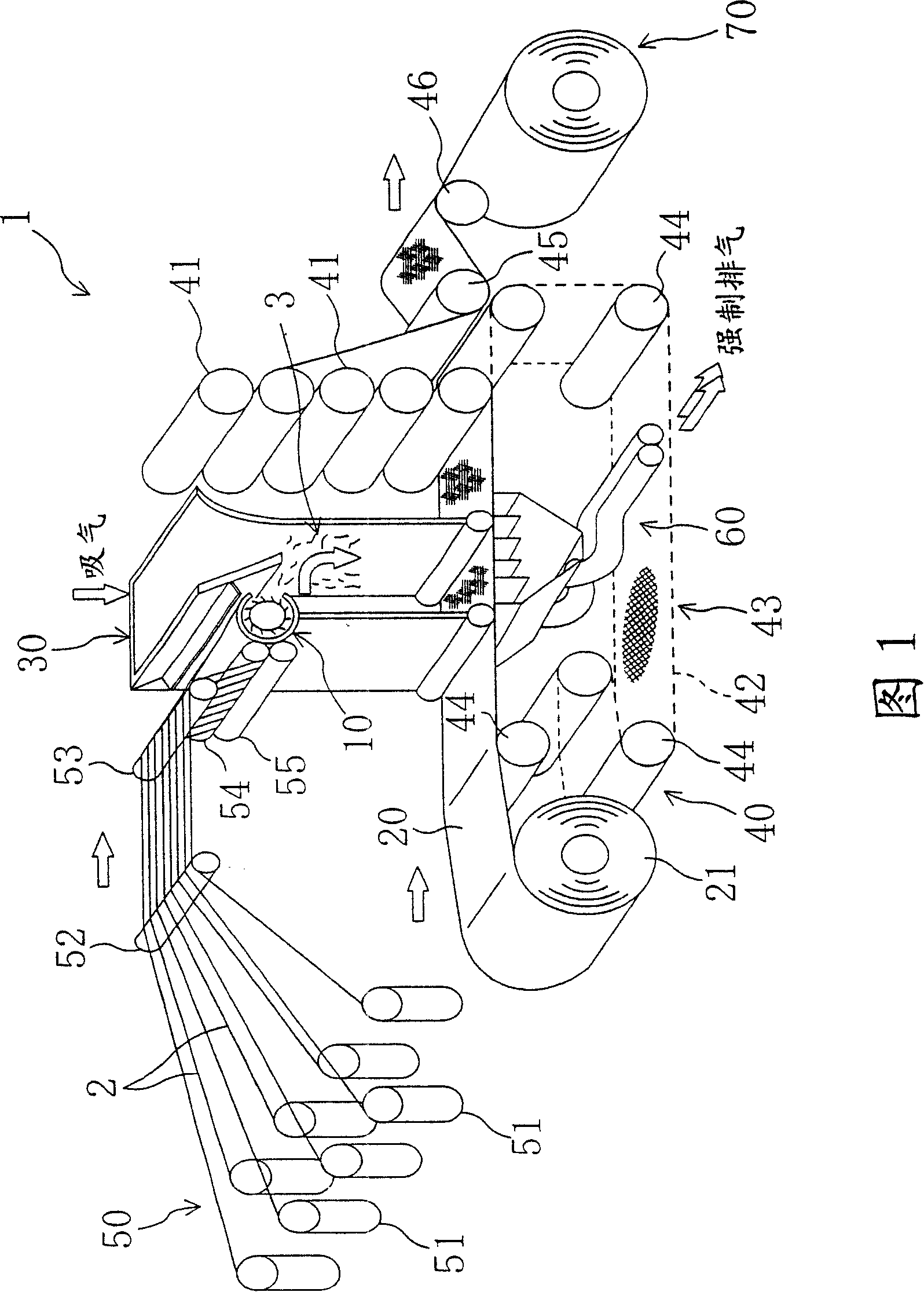
[0098] Figure 9 A first modified example of the above-mentioned embodiment is shown. In this example, the front-back direction of the wind tunnel 30 is reversed from that of the above-mentioned embodiment, and the roller unit 10 is fixed to the back panel 30b. In addition, the back panel 30b is constituted by reversing the same components as the front panel 30a of the above-mentioned embodiment back and forth, and the front panel 30a is constituted by reversing the same components as the back panel 30b of the above-mentioned embodiment back and forth. of. In addition, the short fiber agitating plate 32 is also arranged symmetrically with the above-mentioned embodiment, but the end portion 33a on the facing surface 30a side of the roller unit 10 is arranged lower than the end portion on the roller unit 10 side and the front end 34a of the vortex forming plate 34. , which is the same as the previous example.

[0099] Other structures and effects are the same as those of the ...

Deformed example 2

[0101] Figure 10 A second modified example of the above-mentioned embodiment is shown. In this example, as for the casing 11 of the roller unit 10, it is made into a structure in which the discharge port 11b is formed wider on the side of the upper casing 11c. Further, the second vortex forming plate 11g is fixed to the end portion of the upper case 11c on the discharge port 11b side so as to be substantially parallel to the front plate 30a of the wind tunnel 30 . That is, in this second modified example, the structure in which the second vortex forming plate 11g is provided on the upper portion of the roller unit 10 below the air inlet 30e of the wind tunnel 30 is configured.

[0102] Thus, by enlarging the discharge port 11b of the housing 11, the short fibers 3 can be easily discharged into the wind tunnel 30 even when the short fibers 3 are wound around the needle pieces 14, for example. On the other hand, if the discharge port 11b is simply enlarged, the short fibers 3...


PUM

PropertyMeasurementUnit
lengthaaaaaaaaaa
lengthaaaaaaaaaa

Abstract

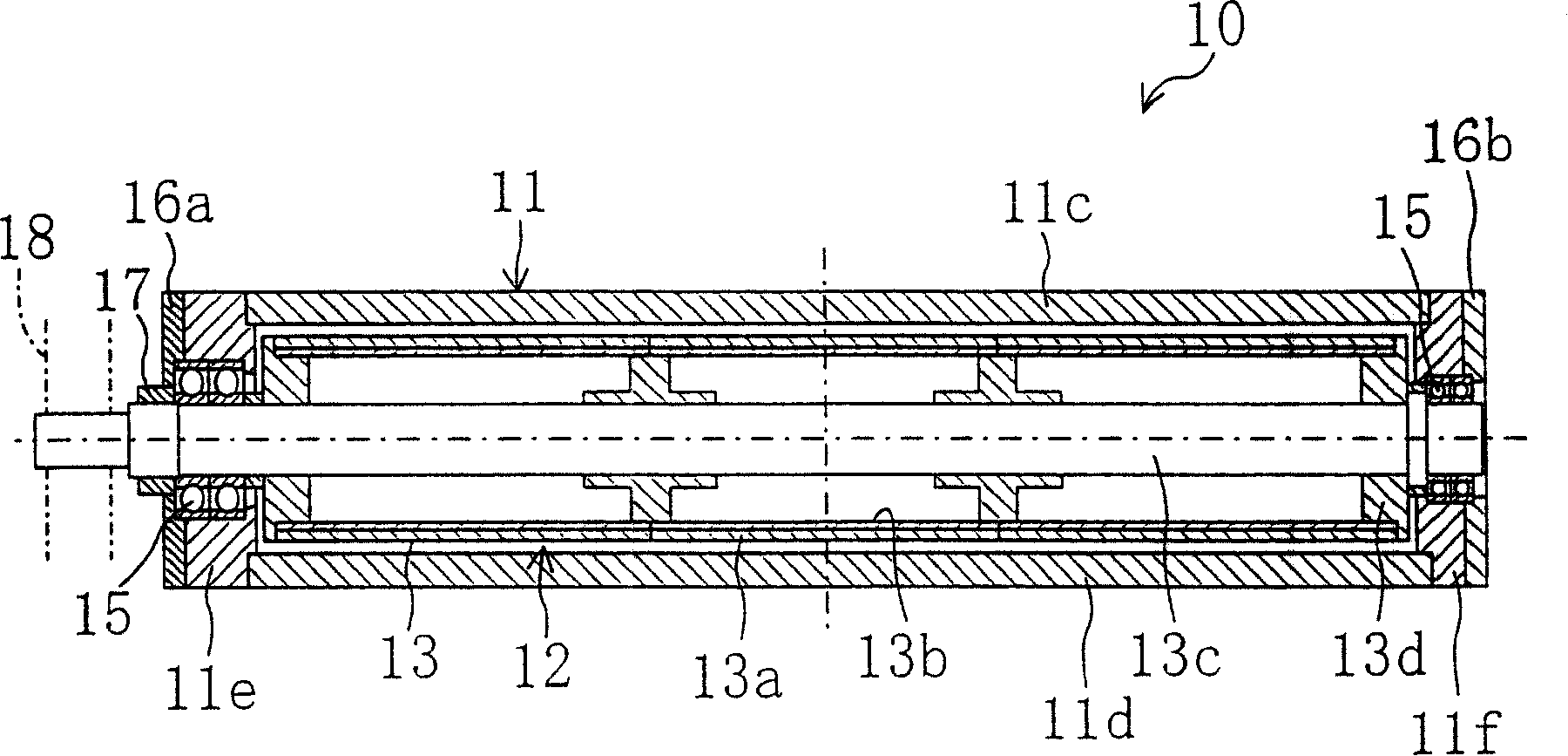
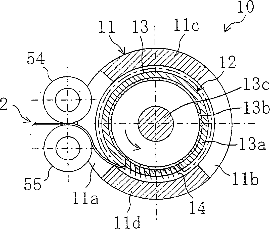
A needle blade roll (12) for forming short fibers from a material capable of formation of artificial cotton in an artificial cotton fabricating apparatus is disclosed which is made up of a roll main body (13) and a large number of needle blades (14) implanted into a peripheral surface of the roll main body (13). In the needle blade roll (12), each needle blade (14) is arranged at a sloping angle relative to a radial line of the roll main body (13) so that its leading end lies ahead of the radial line with respect to the rotational direction of the roll main body (13). This makes it possible to form short fibers the length of which is longer than conventional, thereby fabricating artificial cotton made of such short fibers which are fully intertwined with one another.

Description

technical field [0001] The present invention relates to a pin roll for forming the short fibers from a material capable of forming the artificial cotton in a rayon production apparatus for producing rayon by gathering a plurality of short fibers. Background technique [0002] Conventionally, such rayon manufacturing devices have been constructed as follows: Figure 11 As shown, fiber materials 101 such as yarn or cotton sliver are used to form a plurality of countless short fibers 102 with a fiber length of 1 to 200 mm, and the short fibers 102 are gathered on a mesh conveyor belt 103 or a paper insert (not shown). The conveyor belt 103 etc. are moved on the surface member to continuously produce rayon (for example, refer to JP-A-9-193277). As long as the fiber material 101 can form rayon, various materials including synthetic resin can be used. [0003] In this rayon manufacturing apparatus 100 , generally, a needle roll 106 provided with a plurality of needle pieces 105 o...

Claims


Application Information

Patent Timeline
Patent Type & Authority Patents(China)
IPC IPC(8): D04H1/72D04H1/70D01G25/00D01G1/04B65H27/00D01G15/88D04H17/00
CPCD04H1/72D01G1/02D04H1/58D04H1/70D01G25/00D01G1/04D01G15/88D04H1/732
Inventor 大户德松山本胜年大上功
Owner DAIKIN IND LTD
Why Eureka
Try Eureka