Scanned display with variation compensation

A scanner and memory technology, applied to static indicators, TV system scanning details, instruments, etc., can solve problems such as unacceptable refresh rate

Inactive Publication Date: 2008-04-16
MICROVISION
View PDF11 Cites 2 Cited by
  • Summary
  • Abstract
  • Description
  • Claims
  • Application Information

AI Technical Summary

Problems solved by technology

Therefore, large mirrors and large scan angles can generate unacceptable refresh rates

Method used


Image

  • Scanned display with variation compensation
  • Scanned display with variation compensation
  • Scanned display with variation compensation

Examples


Embodiment Construction

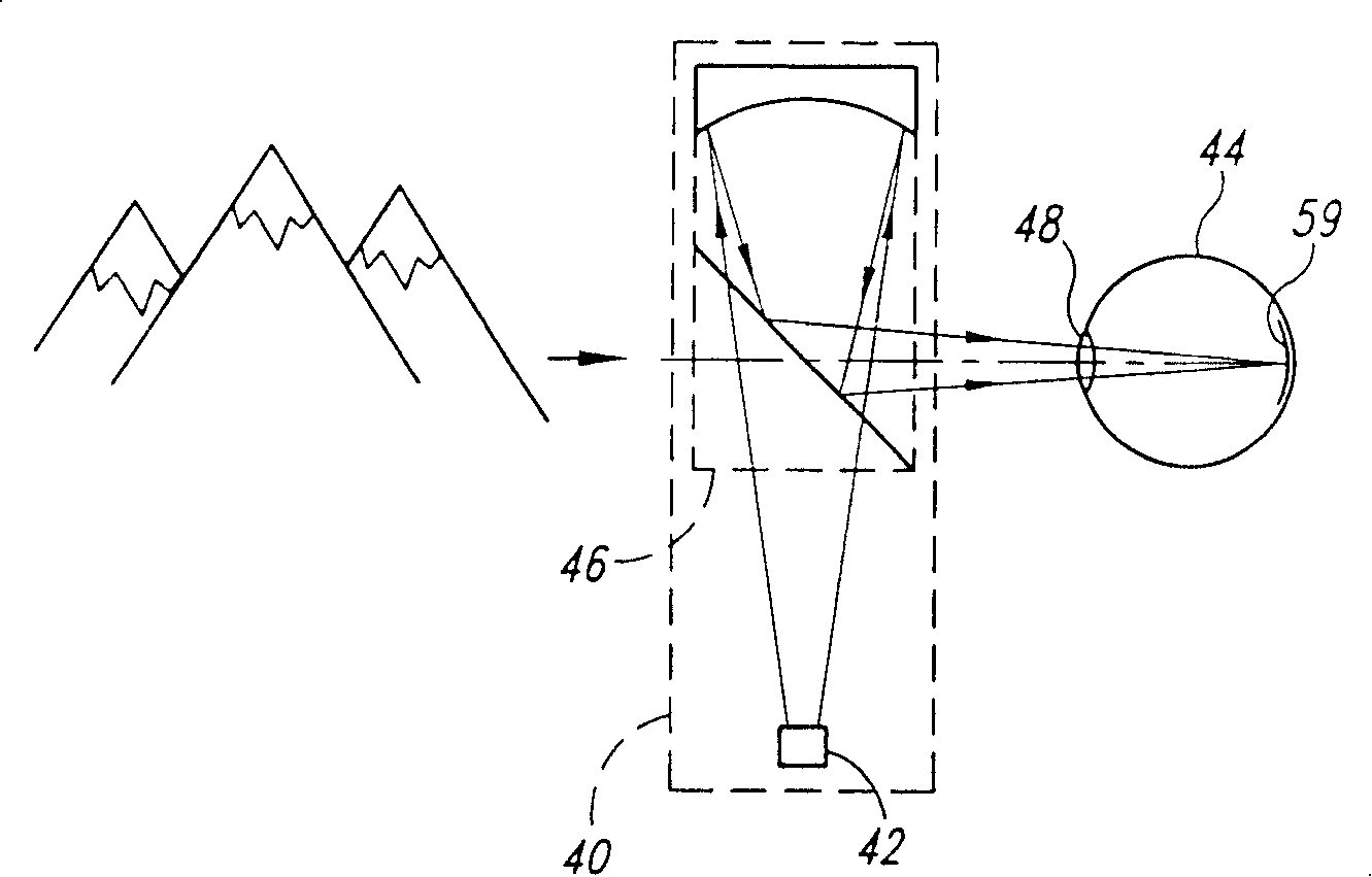
[0067] As shown in FIG. 6 , a scanned beam display 70 according to one embodiment of the present invention is configured for viewing by an observer's eye 72 . Although the display 70 provided herein scans light into the eye 72, the structures and concepts described herein are also applicable to other types of displays, such as projection displays including viewing screens.

[0068] The display 70 includes four main parts, each of which will be described in more detail below. First, control electronics 74 respond to an image signal V from an image source 76 such as a computer, television receiver, video cassette player, DVD player, remote sensor, or the like. IM , providing electrical signals for controlling the operation of the display 70 .

[0069] The second part of the display 70 is a light source 78 which outputs modulated light beams 80 each having a characteristic corresponding to the image signal V IM The information in corresponds to the modulation. Light source 78 ...


PUM


Abstract

A display apparatus includes a scanning assembly that scans about two or more axes, typically in a raster pattern. A light source emits light toward the scannning assembly such that the scanning assembly simultaneously scans more than one of the beams. The light sourced is positioned such that its beam illuminates a discrete region of the image field. The image may be formed from a set of "tiles" where a single sweep of the scanning assembly scans a pluralit yof beams simultaneously. Various approaches to controlling the intensity of the light to compensate for variations in light source response or optical system response, or to balance the response of a tiles system are described. Among these approaches are scaling data in a buffer, active multiplication, or control of a D/A converter.

Description

technical field [0001] The present invention relates to scanning devices, and more particularly to displays and imaging devices of scanned light beams for viewing or collecting images. Background technique [0002] Various techniques may be used to provide a visual display of graphics or video images to a user. In many applications, cathode ray tube displays (CRTs), such as televisions and computer monitors, generate images for viewing. This device suffers from several limitations. For example, CRTs are bulky and power hungry, making them undesirable for portable or head-mounted applications. [0003] Matrix addressable displays such as liquid crystal displays and field emission displays are small and consume little power. However, typical matrix addressable displays use screens that are several inches in diameter. Such screens are of limited use in head-mounted applications, or in applications where the display occupies only a small portion of the user's field of view. ...

Claims


Application Information

Patent Timeline
Patent Type & Authority Patents(China)
IPC IPC(8): G02B26/10G02B26/08G09G3/00H04N3/08G02B27/01G09G3/02
CPCG02B27/017G09G2320/043G02B26/0833G09G2320/041G02B26/101G02B26/10G09G2320/0285G09G3/02G09G3/001G09G2320/0276G09G3/025
Inventor 克拉伦斯T·特格雷恩
Owner MICROVISION
Why Eureka
Try Eureka