Parameter checkout method and device for object being checked
An object and parameter technology, which is used in the field of parameter detection and detection devices for detecting objects, and can solve the problems that the retardation and low transmittance of the liquid crystal layer cannot be correctly detected.
- Summary
- Abstract
- Description
- Claims
- Application Information
AI Technical Summary
Problems solved by technology
Method used
Image
Examples
no. 1 example
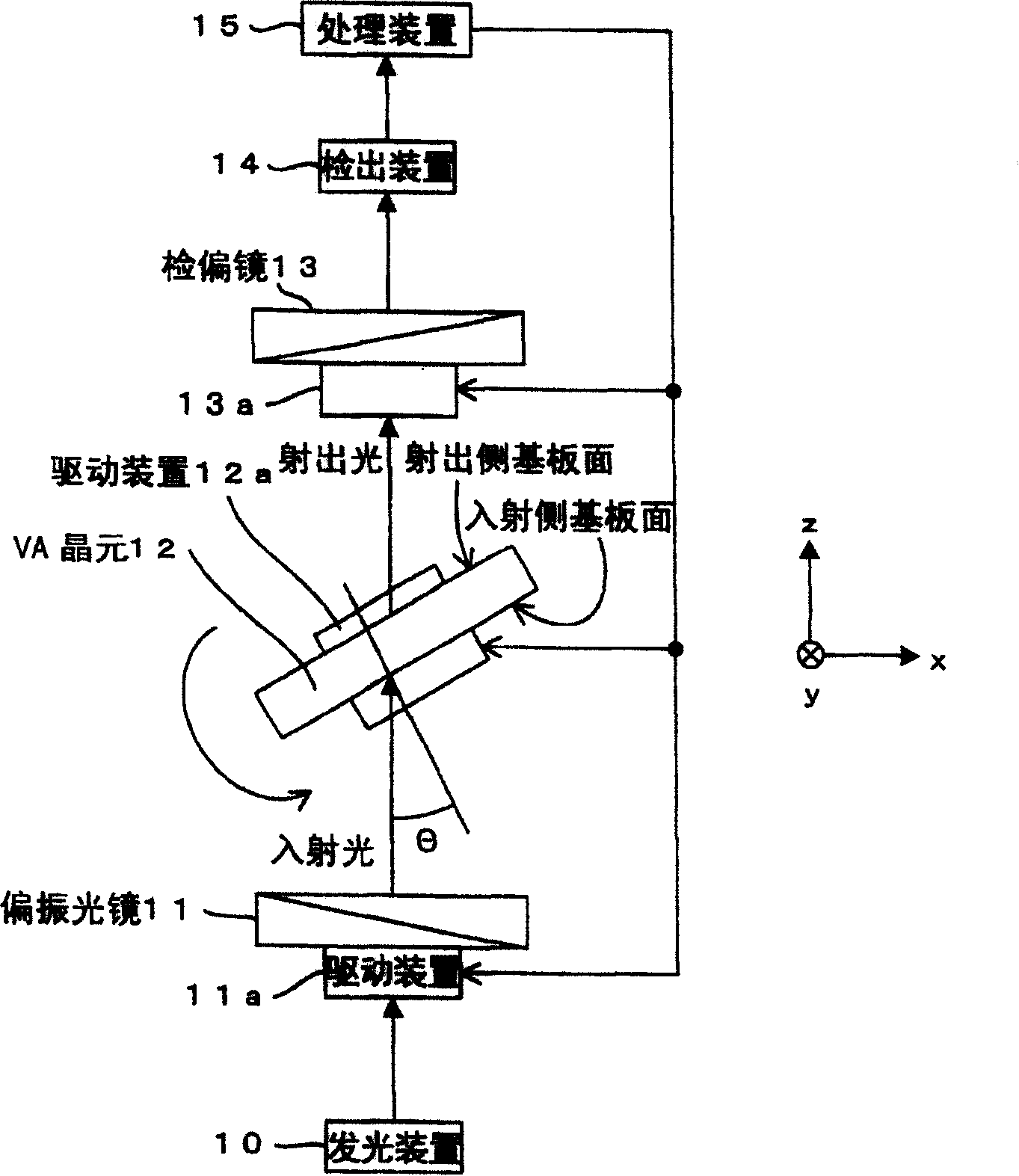
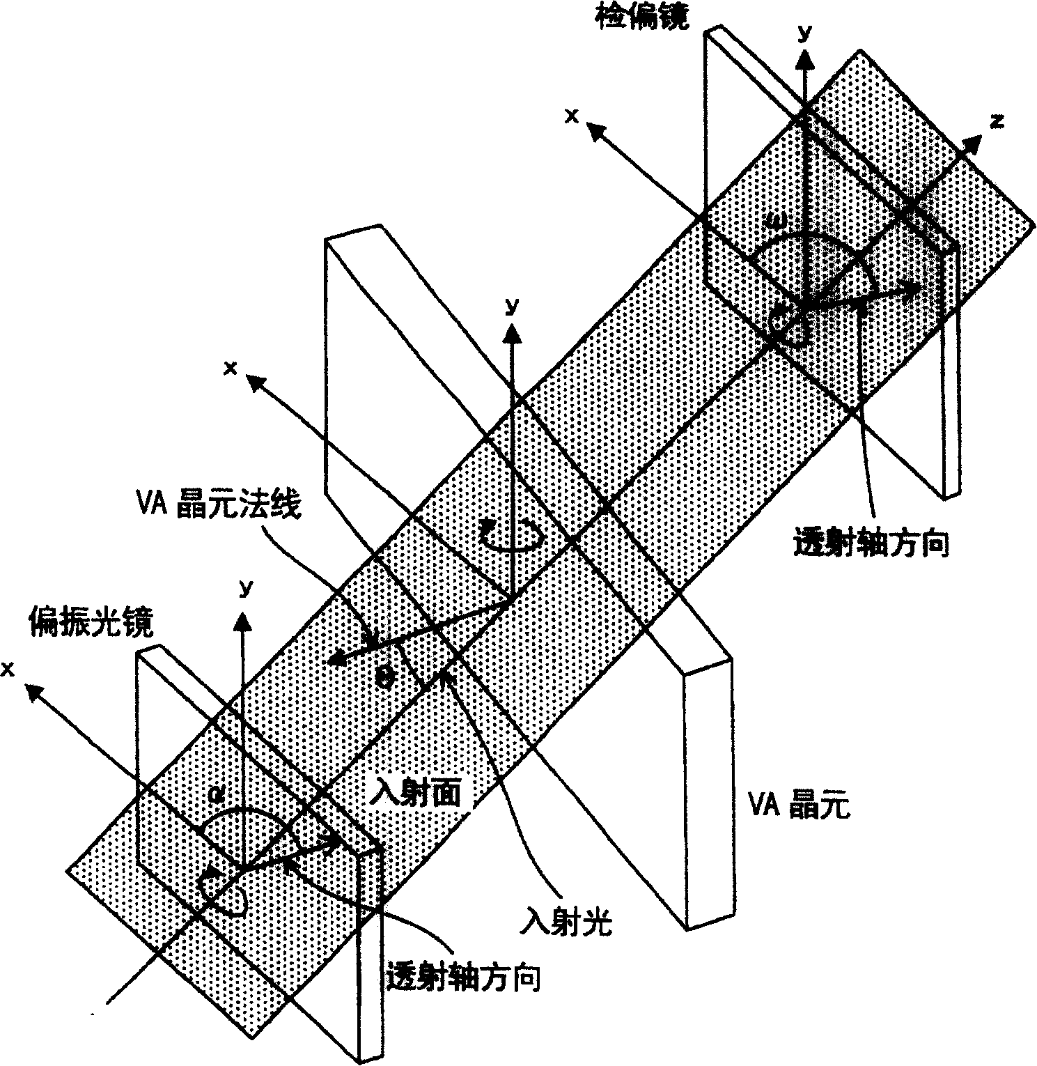
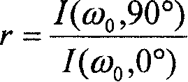
[0222] In the first embodiment, the inclination angle ω of the transmission axis direction of the analyzer 13 with respect to the incident surface (hereinafter referred to as "transmission axis direction ω of the analyzer 13") is set to an arbitrary angle. In addition, the inclination angle α of the transmission axis direction of the polarizer 11 with respect to the incident surface (hereinafter referred to as "the transmission axis direction α of the polarizer 11") is set to an angle (α=0°) parallel to the incident surface ) and the angle perpendicular to the incident plane (α=90°). The transmitted light intensity was measured in each state. Then, the parameters of the VA element 12 (detection object) are detected using the ratio r of the measured transmitted light intensity.
[0223] Set the transmission axis direction ω of the analyzer 13 to an arbitrary angle ω 0 in the direction (towards the angle ω 0 direction). In addition, the transmission axis direction α of the p...
no. 2 example
[0302] [Equation 13] expressing the transmitted light intensity when the direction of the transmission axis of the polarizer is set in the direction of α, and the direction of the transmission axis of the analyzer is set in the direction of ω, does not change at all even if α and ω are replaced . That is, the polarizer described in the first embodiment can be replaced by an analyzer, and the analyzer can be replaced by a polarizer.
[0303] In the second embodiment, in the state where the transmission axis direction α of the polarizer 11 is set to a direction at an arbitrary angle, the transmission axis direction ω of the analyzer 13 is set to a direction parallel to the incident surface ( ω=0°) and the direction perpendicular to the incident surface (ω=90°), the respective transmitted light intensities were measured. Thus, the parameters of the VA element 12 (detection object) are detected using the ratio r of the measured transmitted light intensity.
[0304] When the tran...
no. 3 example
[0365] In the first or second embodiment, the transmission axis direction ω of the analyzer 13 or the transmission axis direction α of the polarizer 11 is set to a specific direction in order to obtain the ratio r of the transmitted light intensity. Here, the setting operation of the transmission axis direction α of the polarizer 11 and the transmission axis direction ω of the analyzer 13 can be easily performed.
[0366] In the third embodiment, the transmission axis direction α of the polarizer 11 is set to be a direction at an arbitrary angle. In this state, the transmission axis direction ω of the analyzer 13 is set to any direction of three or more different angles, and the respective transmitted light intensities are measured. Then, the retardation R of the liquid crystal layer of the VA cell 12 is detected using the measured three or more transmitted light intensities.
[0367][Formula 13], which represents the transmitted light intensity when the direction of the tran...
PUM
| Property | Measurement | Unit |
|---|---|---|
| thickness | aaaaa | aaaaa |
Abstract
Description
Claims
Application Information
 - R&D
- Intellectual Property
- Life Sciences
- Materials
- Tech Scout
- Unparalleled Data Quality
- Higher Quality Content
- 60% Fewer Hallucinations
Browse by: Latest US Patents, China's latest patents, Technical Efficacy Thesaurus, Application Domain, Technology Topic, Popular Technical Reports.
© 2025 PatSnap. All rights reserved.Legal|Privacy policy|Modern Slavery Act Transparency Statement|Sitemap|About US| Contact US: help@patsnap.com


