Robot for industry
An industrial robot and robot technology, applied in the direction of manipulators, manufacturing tools, conveyor objects, etc., can solve the problems of large intervals of conveyed objects, expand the moving range of industrial robots, etc., and achieve easy, rapid and correct transportation and operation of position control good sex effect
- Summary
- Abstract
- Description
- Claims
- Application Information
AI Technical Summary
Problems solved by technology
Method used
Image

Examples
no. 1 Embodiment approach
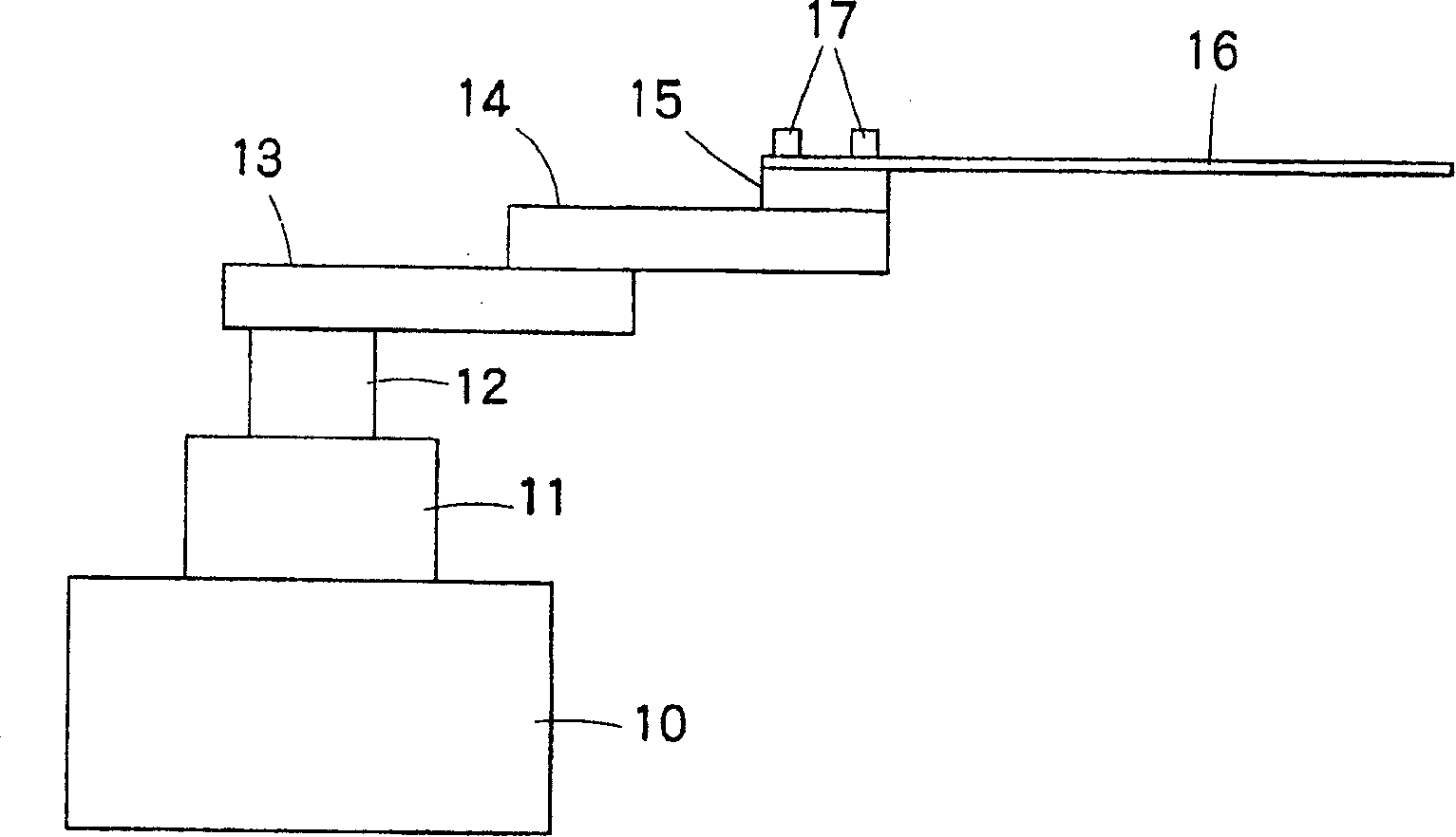
[0031] figure 1 It is a figure which shows an example of the industrial robot to which this invention was applied, 10 is a base, 11 is a rotating table, 12 is a lifting and rotating shaft, 13 is a 1st rotating arm, 14 is a 2nd rotating arm, 15 is a hand , 16 is a fork.
[0032] The first rotating arm 13 and the second rotating arm 14 are arms that rotate on a horizontal plane, and the hand 15 at the tip of the second rotating arm can be moved in the radial direction of the elevating and rotating shaft 12 so as to rotate in opposite directions to each other. . At this time, the hand 15 rotates on the second rotating arm 14 in conjunction with the rotation of the first rotating arm 13 and the second rotating arm 14 , and keeps the orientation of the fork 16 constant. In addition, the hand 15 can also be rotated separately from the above-mentioned linkage. Furthermore, the hand 15 moves up and down together with the lifting and lowering of the lifting / rotating shaft 12 . In a...
no. 2 Embodiment approach
[0044] Next, refer to Figure 8 to Figure 12 A second embodiment of the industrial robot of the present invention will be described. In addition, the industrial robot to which the present invention is applied is the same as the first embodiment. figure 1 Shown robot, with regard to the fork frame 16 that is installed on the hand 15, for Figure 1 to Figure 7 Components common to the first embodiment are denoted by the same reference numerals, and detailed description thereof will be omitted.
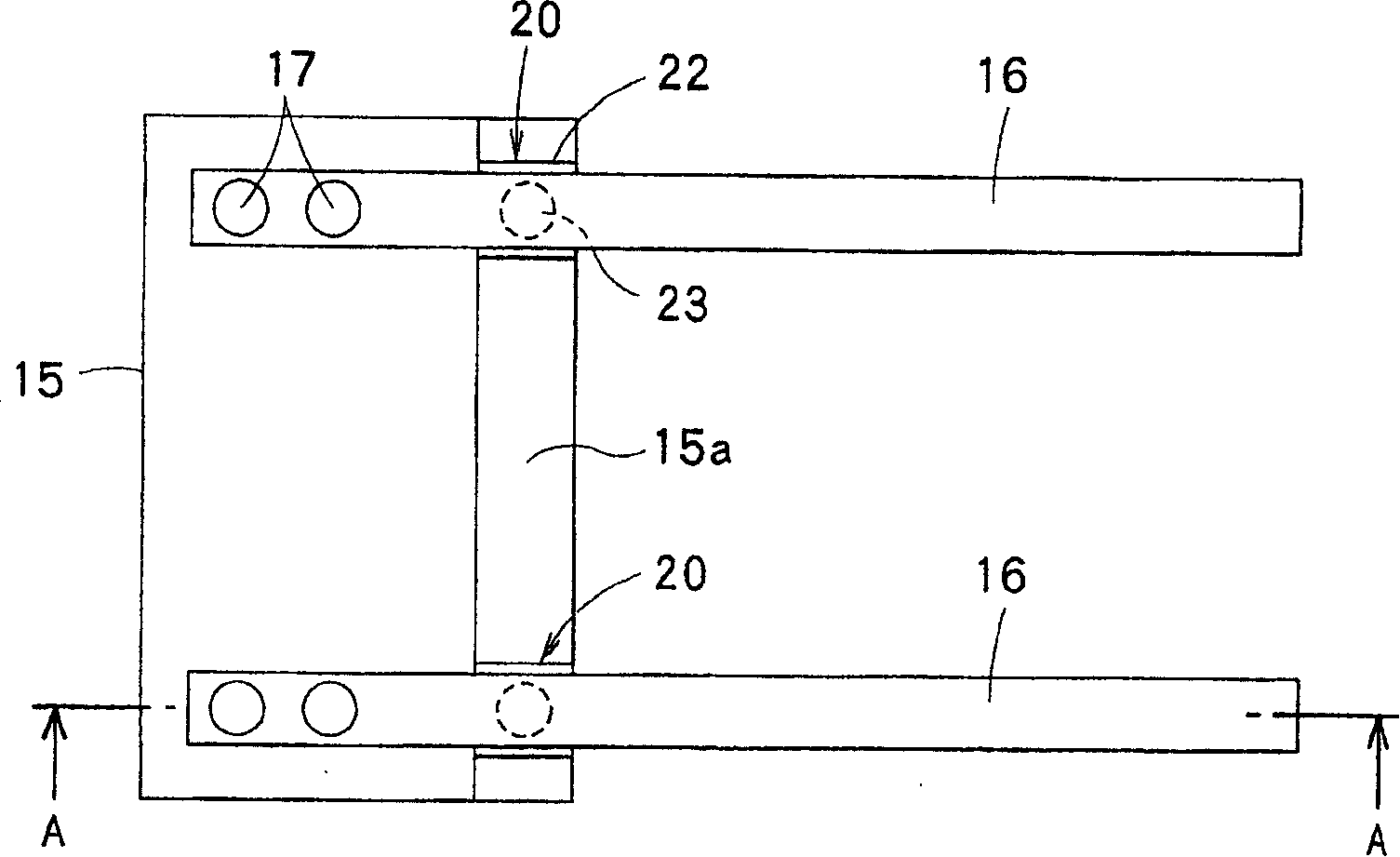
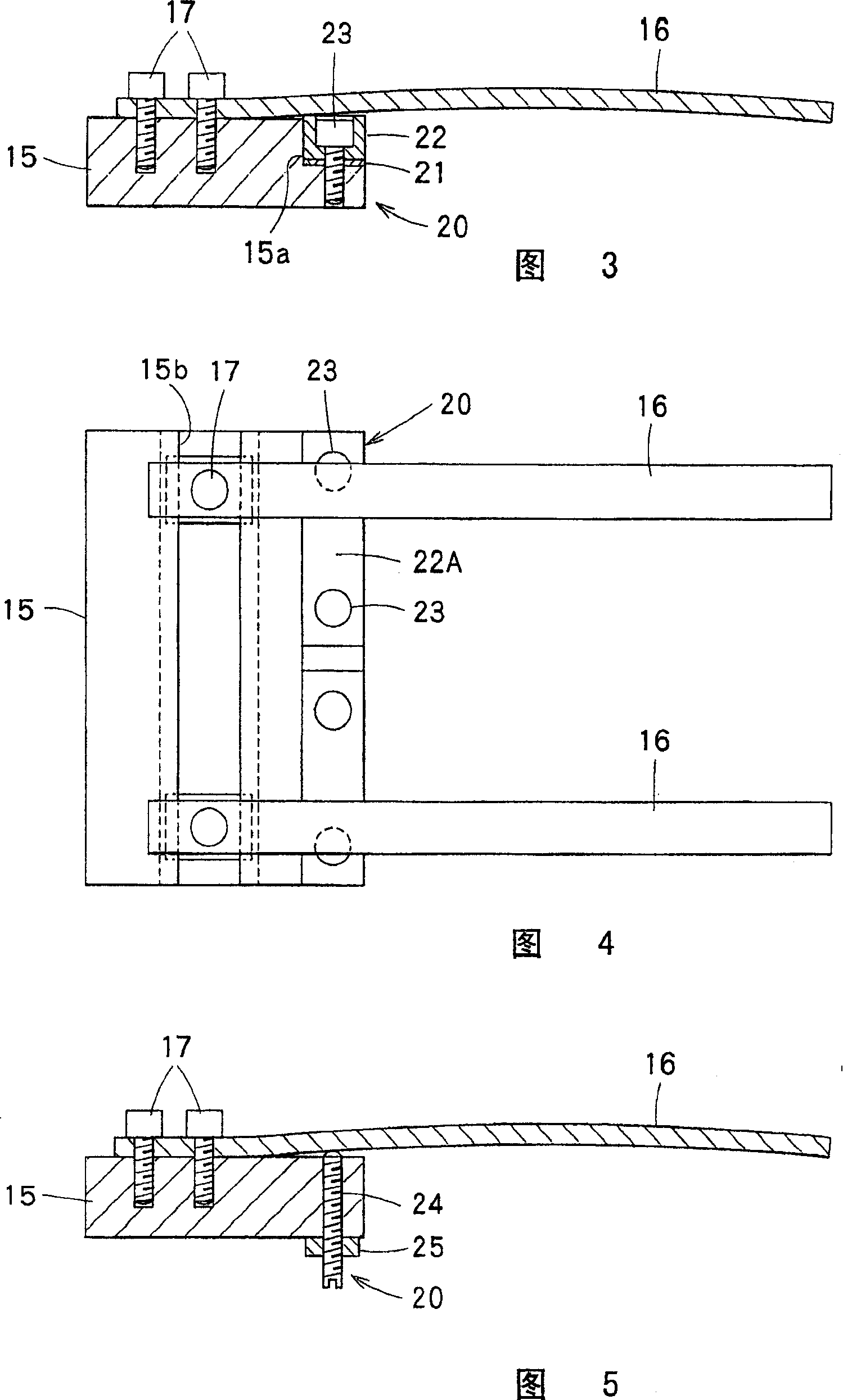
[0045] Figure 8 It is an enlarged plan view showing the hand 15 and the fork 16 in detail. as it should Figure 8 As shown, the base ends of a pair of forks 16 are fixed to the upper surface of the hand 15 with bolts 17, and the forks 16, 16 are attached to the hand 15 in a mutually parallel and horizontal posture. Figure 9 yes Figure 8 A sectional view of the B-B line, as in the Figure 9 As shown, on the upper surface of the hand 15, on the position closer to the front end si...
no. 3 Embodiment approach
[0054] Next, refer to Figure 13 to Figure 19 A third embodiment of the present invention will be described. Additionally, for Figure 1 to Figure 7 Components common to the first embodiment are denoted by the same symbols, and detailed descriptions thereof are omitted.
[0055] Figure 13 It is an enlarged top view showing the hand 15 and the fork 16 in detail, Figure 14 yes Figure 13 Sectional view of E-E line. The fork frame 16 is installed on the hand 15 by the first mounting mechanism 60 composed of bolts 61 and lock nuts 62, 63 at the first position on its base end side, so as to move from the above-mentioned first position to the fork frame 16. It is mounted on the hand 15 through a second mounting mechanism 64 composed of bolts 65 and lock nuts 66 and 67 at a second position away from the front end side by a predetermined amount.
[0056] as it should Figure 13 to Figure 14 The illustrated embodiment is constructed in such a way that after changing the height...
PUM
 Abstract
Description
Claims
Application Information
 - R&D
- Intellectual Property
- Life Sciences
- Materials
- Tech Scout
- Unparalleled Data Quality
- Higher Quality Content
- 60% Fewer Hallucinations
Browse by: Latest US Patents, China's latest patents, Technical Efficacy Thesaurus, Application Domain, Technology Topic, Popular Technical Reports.
© 2025 PatSnap. All rights reserved.Legal|Privacy policy|Modern Slavery Act Transparency Statement|Sitemap|About US| Contact US: help@patsnap.com