
Flow control method for Ether net passive light network and device used in said method

A passive optical network and flow control technology, which is applied in the direction of data exchange network, digital transmission system, electrical components, etc., can solve the problems of decreased upstream bandwidth utilization, lack of status reporting mechanism, and unknown ONU status, etc.

Inactive Publication Date: 2008-05-14
FENGHUO COMM SCI & TECH CO LTD
View PDF4 Cites 0 Cited by
  • Summary
  • Abstract
  • Description
  • Claims
  • Application Information

AI Technical Summary

Problems solved by technology

However, since there is no flow control mechanism between the OLT and the ONU, the OLT does not know the state of the ONU, and the OLT may continue to send data frames to this ONU, so a large number of frame loss may occur due to insufficient buffer space on the ONU
Similar frame loss phenomena may also occur in the upstream direction. The occurrence of these phenomena is due to the lack of a status reporting mechanism between the OLT and the ONU
[0007] Second, if the problem of frame loss in EPON system is solved by high-level protocol, it will seriously affect the network throughput
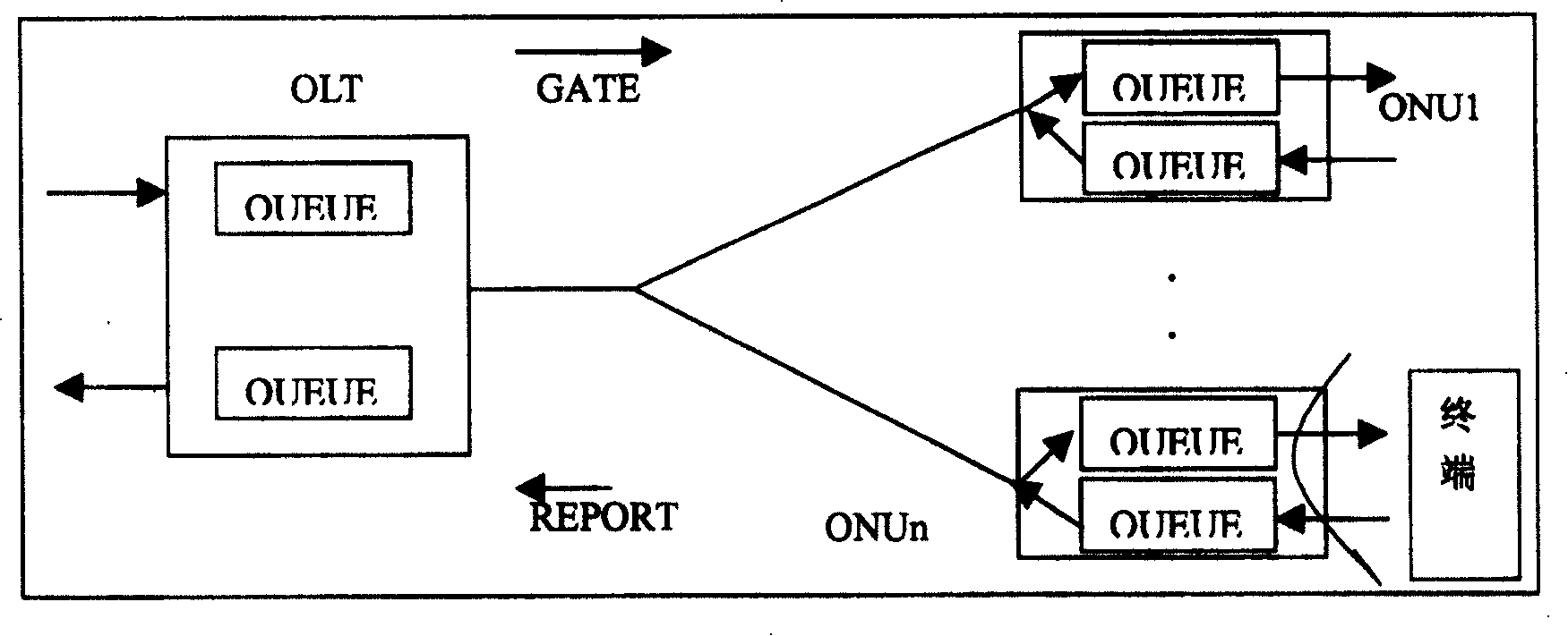
However, the result of the application of the conventional GATE / REPORT mechanism will reduce the utilization rate of the uplink bandwidth, and there will be a lot of frame loss during congestion.
Because when congestion occurs, the GATE message restricts the ONU from sending data to the OLT for a certain period of time. During this period of time, the ONU still continues to send data, causing the OLT to lose a lot of frames due to congestion.

Method used


Image

  • Flow control method for Ether net passive light network and device used in said method
  • Flow control method for Ether net passive light network and device used in said method
  • Flow control method for Ether net passive light network and device used in said method

Examples


Embodiment Construction

[0082] Specific embodiments of the present invention will be explained in detail below in conjunction with the accompanying drawings.

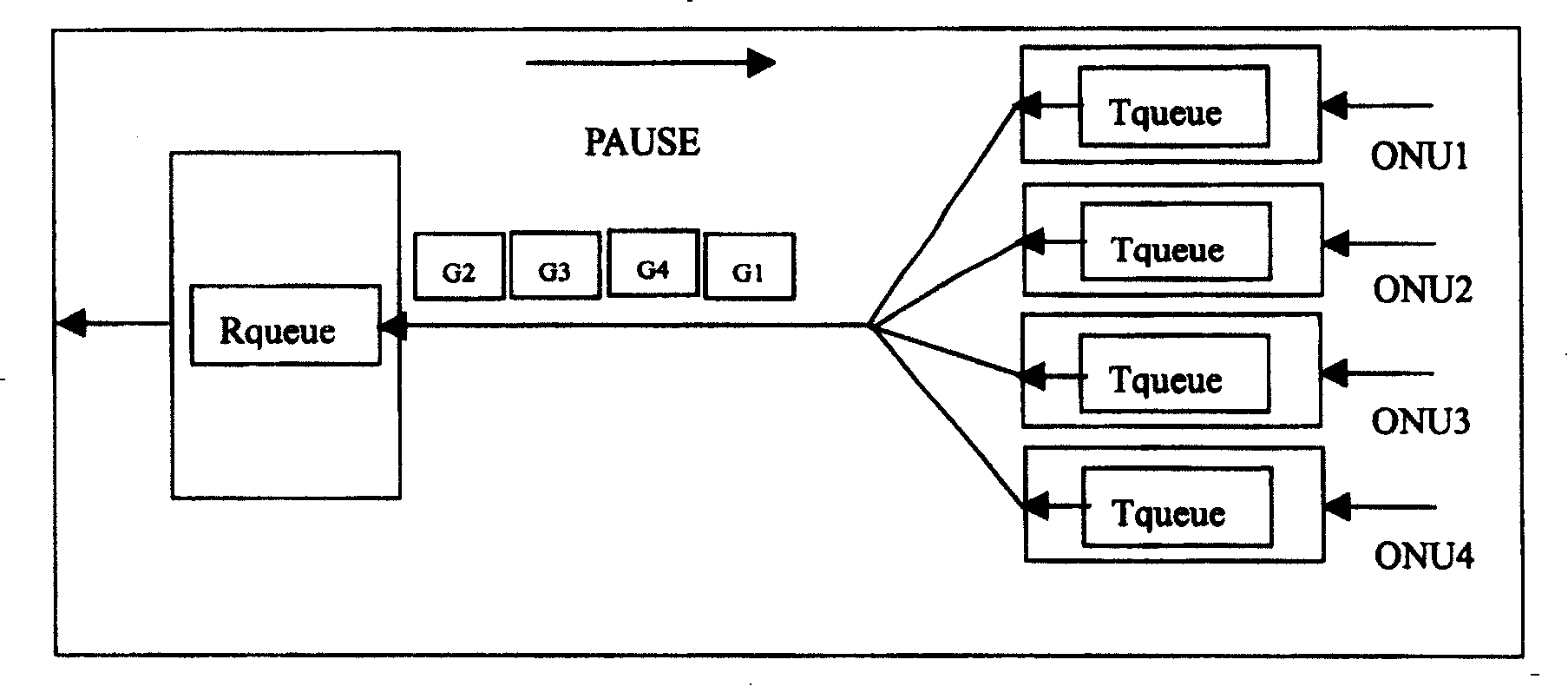
[0083] exist image 3 with Figure 4 You can see the upstream bandwidth allocation under the control of the GATE / REPORT mechanism in image 3 The reference signs G1, G4, G3, and G2 in represent the bandwidth allocated by the OLT to ONU1, ONU4, ONU3, and ONU2 in turn through the GATE frame, that is, ONU1 to 4 send uplink data frames to the OLT in the order of allocation. from Figure 4 It can be seen that each ONU sends data frames within the time period assigned to itself according to the authorization. Such as image 3 , 4 As shown in , each ONU sends data frames to the OLT in the order of 1, 4, 3, and 2, regardless of whether the buffer in the OLT has sufficient capacity, so frame loss may occur.

[0084] Image 6 It is a schematic diagram of the device used for upstream flow control in the present invention, wherein the OLT is compos...


PUM


Abstract

This invention relates to a flow control method in Ethernet passive optical network (EPON) and its device which can control the point-to-point flow between the optical line terminal optical line(PNIU) and prevent storage volumes of OLT or ONU. This invention introduces a pause system in the EPON system to realize the flow control between OLT and ONU.

Description

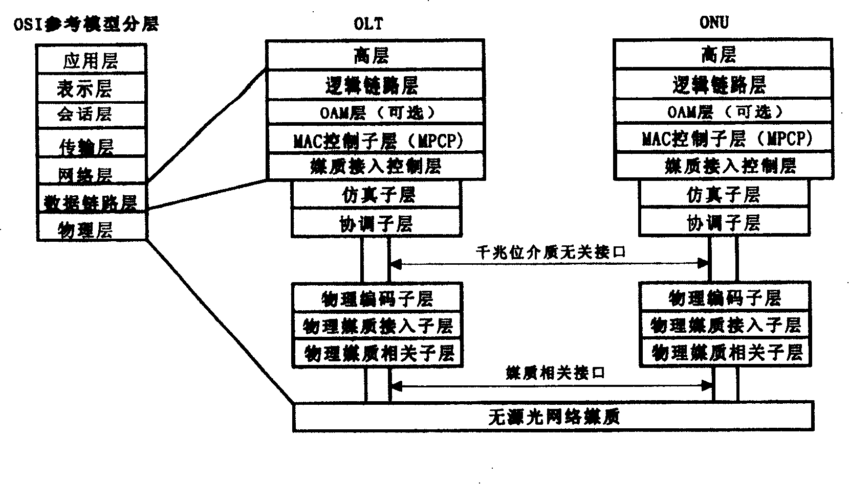
technical field [0001] The present invention relates to a flow control method of an Ethernet passive optical network (EPON) and a device used in the method, in particular to an optical line terminal (OLT) and an optical network unit device in a passive optical network based on Gigabit Ethernet An implementation method of flow control between (ONU). Background technique [0002] EPON is composed of an optical line terminal (OLT) at the central office, several optical network units (ONU) at the remote end, and a passive optical distribution network (ODN). In the ODN, the two optical transmission directions use two wavelengths respectively. The signal is defined as the downlink direction from the OLT to the ONU, and is sent in broadcast mode, using time division multiplexing (TDM) technology; while the signal is defined as the uplink direction from the ONU to the OLT. , using time division multiple access (TDMA) technology. [0003] figure 1 It is the corresponding relations...

Claims


Application Information

Patent Timeline
Patent Type & Authority Patents(China)
IPC IPC(8): H04L29/08H04L12/56H04L12/801
Inventor 何岩杨柳陈丽张傲
Owner FENGHUO COMM SCI & TECH CO LTD
Learn More