
Pneumatic fiber nesting device

A fiber and concentrator technology, applied in textiles and papermaking, drafting equipment, spinning machines, etc., can solve problems such as inconvenient loading and unloading operations

Inactive Publication Date: 2008-05-28
DONGTAI TEXTILE MASCH CO LTD
View PDF6 Cites 0 Cited by
  • Summary
  • Abstract
  • Description
  • Claims
  • Application Information

AI Technical Summary

Problems solved by technology

In addition, the operation of loading and unloading the spring-loaded cradle also has the disadvantage of being inconvenient.

Method used

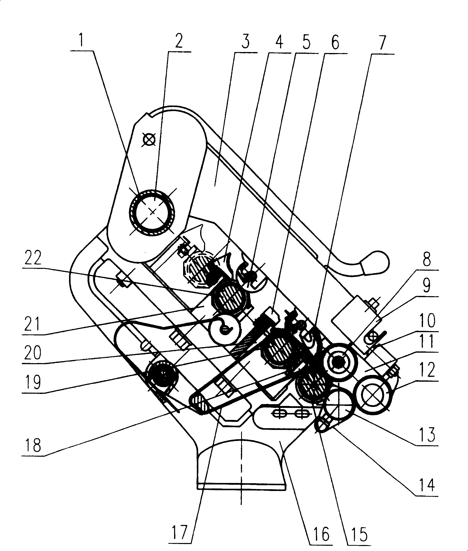
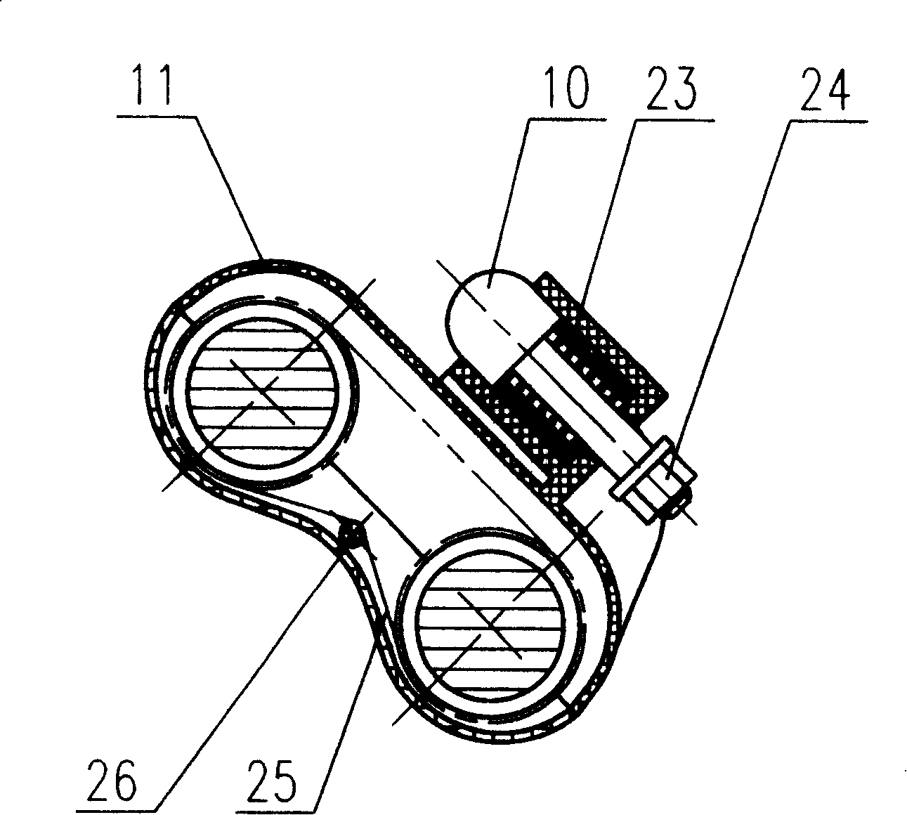

Image

  • Pneumatic fiber nesting device
  • Pneumatic fiber nesting device
  • Pneumatic fiber nesting device

Examples


Embodiment Construction

[0016] exist figure 1 In the shown pneumatic fiber gathering device, the front roller 15 is rotatably supported by the roller bearing at the front end of the roller seat 16; Cradle 3, each cradle 3 corresponds to each spindle. The cradle support 1 is a circular tubular support, which is positioned by positioning pins. The cradle support 1 can also be a polygonal support such as a regular hexagonal tubular support. An air bag 2 is installed in the tubular support lumen of the cradle support 1 to pass The lever makes the weighting arm obtain the pressurized force. On the roller seat 16, the middle roller 19 and the rear roller 22 are rotatably supported by the middle roller slide seat 20 and the rear roller seat 21 respectively. On the positions of the cradle 3 corresponding to the front roller 15, the middle roller 19 and the rear roller 22, the front top roller 8, the apron iron roller assembly 7 and the rear top roller 5 are clamped.

[0017] The front side of front roller...


PUM


Abstract

The present invention discloses a kind of assembly device for pneumatic fiber out of ring frame, comprising a forward drawing roller pair with front roller and a front leather roller clamping the front end of a rocking frame, and an assembly twist retarding pair with a suction hose and an assembly leather roller. The said assembly twist retarding pair is located in the front side of the front drawing roller pair; the said suction hose has a suction rift where there is a permeable conveyer belt operating through a sliding socket joint. The said rocking frame is a pneumatic device for increasing pressure, which bears the supporting stand of the rocking frame. The inflatable bag is placed in the pipe cavity of the supporting stand for the rocking frame. The pneumatic fiber assembly device has not only avoided 'the plus-twisting delta area' and enabled the fiber ribbon to become close and tight, but also kept a stable plus-pressure through the rocking frame and a little difference in pressure among different spindles, thus bringing about the best composite spinning capacity.

Description

technical field [0001] The invention relates to a ring spinning frame, in particular to a fiber sliver gathering and compacting device of the drafting mechanism of the spinning frame. Background technique [0002] The draft mechanism is one of the important parts of the ring spinning frame. The roving or sliver can be evenly drawn and thinned to the number required by the yarn only after passing through the drafting mechanism. Therefore, the structure type and pressure stability of the drafting mechanism will directly affect the yarn evenness, The pros and cons of quality indicators such as hairiness and strength. [0003] On the traditional ring spinning machine, the fiber strands always leave the front roller nip of the drafting mechanism with an obvious width due to the influence of the roller pressure in the drafting area, and the so-called " Due to the existence of the twisting triangle area, the distribution of force on the fibers in the sliver is uneven during the t...

Claims


Application Information

Patent Timeline
Patent Type & Authority Patents(China)
IPC IPC(8): D01H5/70D01H5/26
Inventor 朱鹏王平周祥
Owner DONGTAI TEXTILE MASCH CO LTD
Learn More