

Floating platform on sea with refuge device
A floating platform and refuge device technology, which is applied to floating buildings and other directions, can solve the problems of increasing the construction cost of offshore platforms
- Summary
- Abstract
- Description
- Claims
- Application Information
AI Technical Summary
Problems solved by technology
Method used
Image

Examples
Embodiment Construction
[0014] The present invention is specifically described below in conjunction with accompanying drawing:
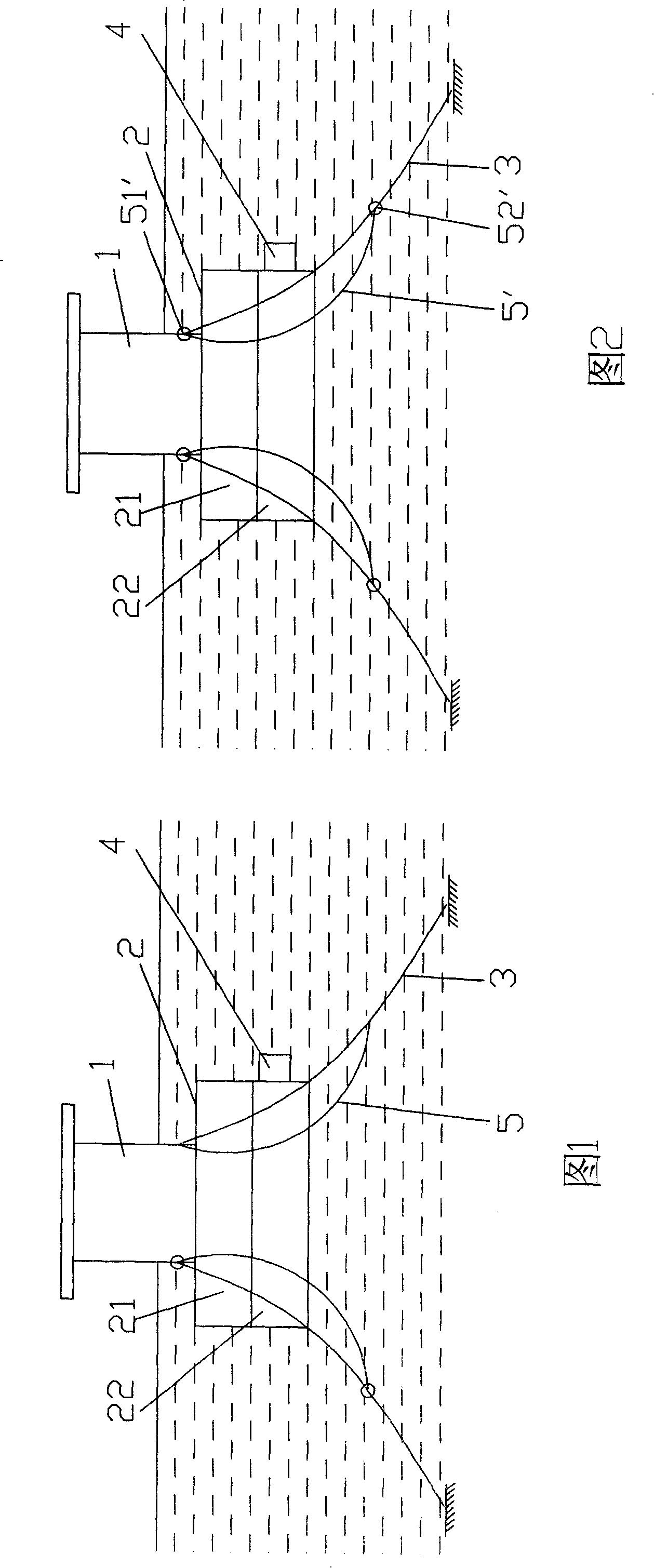
[0015] As shown in Figure 1, the offshore floating platform with a refuge device of the present invention includes a platform body 1, which is provided with anchoring cables 3 fixed on the seabed, and the platform body 1 is partially waterproofed, and the platform body 1 Below is provided with floating body 2, and described floating body 2 is provided with mutually independent air cavity 21, water cavity 22, and air cavity 21 is a fixed buoyancy device, is filled with air in it, buoyancy is fixed, is used for balancing the weight of platform itself, and water cavity 22 is an adjustable buoyancy device, which can be filled with water or discharged, and is used to stabilize the platform structure and adjust the overall buoyancy of the platform in the working state, during the dive process and in the refuge position. The power system 4 for diving and lifting, the power system ...
PUM
 Abstract
Description
Claims
Application Information