

Tuning-type micro electro-mechanical gyroscope
A micro-electromechanical gyroscope and gyro rotor technology is applied in the direction of rotating gyroscope and gyro effect for speed measurement, measuring device, etc. and other problems, to achieve the effect of heavy weight, simple structure, and stable rotation speed.
- Summary
- Abstract
- Description
- Claims
- Application Information
AI Technical Summary
Problems solved by technology
Method used
Image

Examples
Embodiment Construction
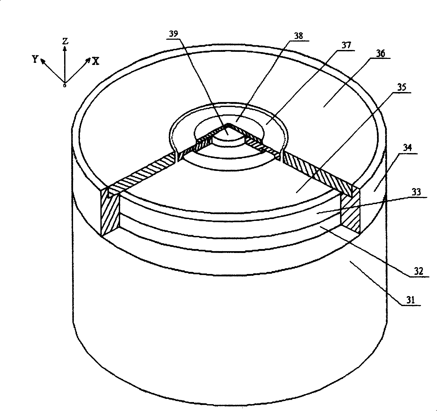
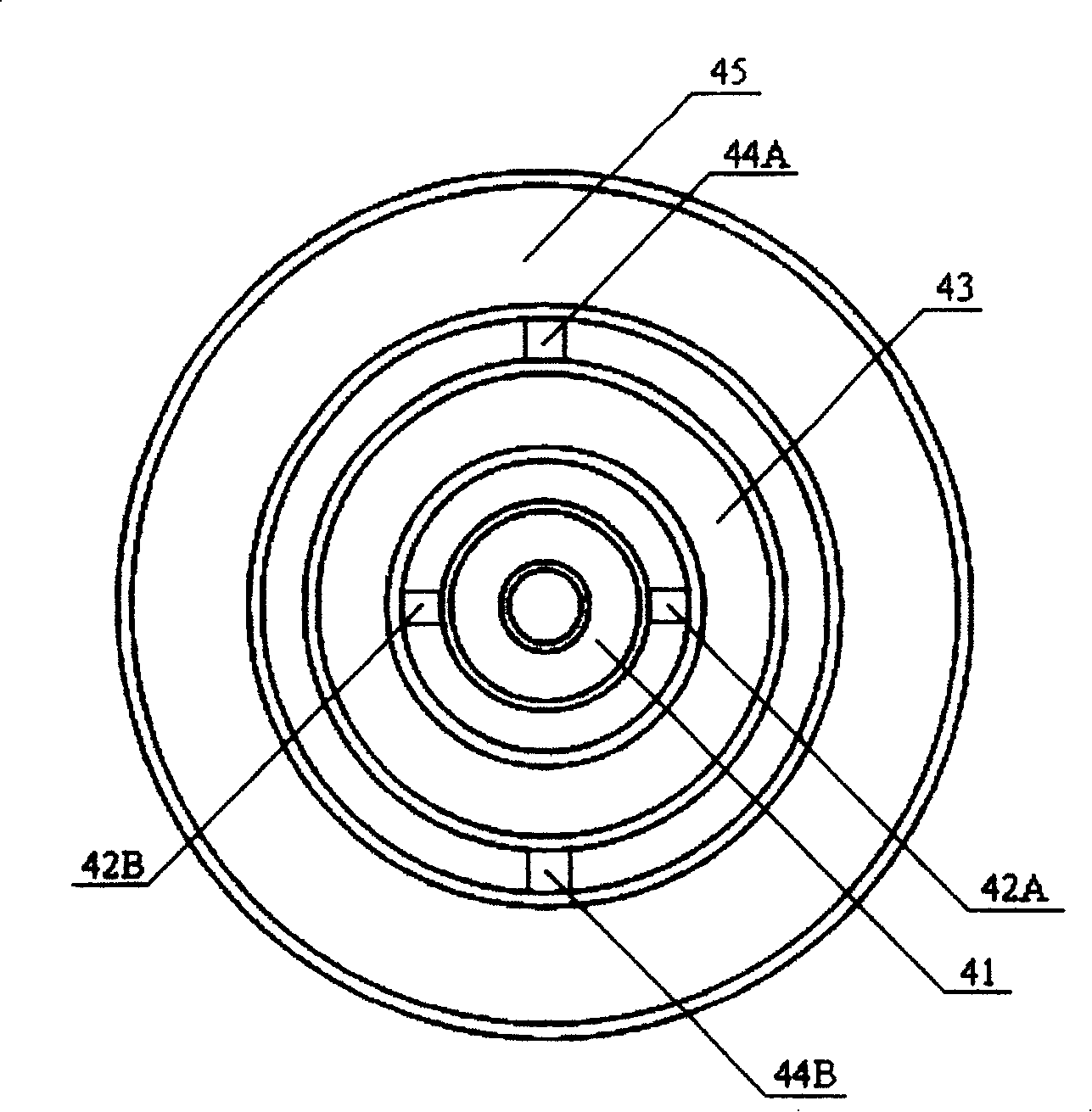
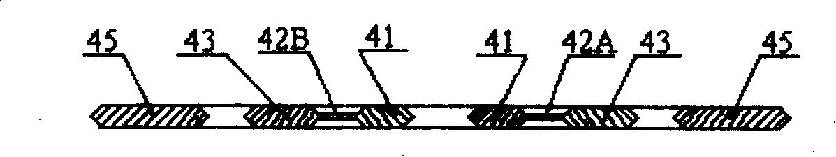
[0023] A tuned micro-electromechanical gyro involving measurement technology, including a motor 31, a gyro rotor / balancing ring 35 is provided on a motor drive shaft 39, and capacitor upper and lower plates are respectively provided above and below the gyro rotor / balancing ring 35 33, 36 and fixed by the fixed ring 34, on the fixed ring 34 is provided with a wire ring 32 for guiding the output signal of the upper and lower plates of the capacitor, and the gyro rotor / balance ring 35 is composed of the inner ring 41, the middle ring 43 and the outer The inner ring 41 is fixedly connected with the drive shaft of the driving motor, the middle ring 43 is a balance ring, and the outer ring 45 is a rotor body. The inner ring and the balance ring are connected by a pair of inner torsion bars 42A, 42B. The balance ring and the rotor The body is connected by a pair of external torsion rods 44A, 44B, and a baffle plate 37 for preventing the rotor from colliding with the capacitor plate is...
PUM
 Abstract
Description
Claims
Application Information