Lateral stress sensing system based on double-mode photon cystal coptical fibre and implementing method
A technology of photonic crystal fiber and transverse stress, which is applied in the direction of transmitting sensing components, clad optical fibers, optical waveguides and light guides with optical devices, and can solve the difficulty of transverse stress detection and the absence of photonic crystal fiber transverse stress sensing and Detection and other issues
- Summary
- Abstract
- Description
- Claims
- Application Information
AI Technical Summary
Problems solved by technology
Method used
Image
Examples
Embodiment 1
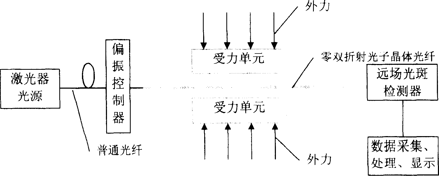
[0064] Embodiment 1; Zero birefringence dual-mode photonic crystal fiber transverse stress (strain) sensing system;
[0065] attached figure 1As shown, the optical fiber in the figure is a zero-birefringence photonic crystal fiber, and the output light wavelength of the laser light source is 633nm. The optical fiber at this wavelength is in a dual-mode working state, supporting fundamental mode and second-order even mode; In the detection area, after the polarization controller, only the fundamental mode and the second-order even mode of polarization in the x direction remain; the dislocation is coupled into the photonic crystal fiber, and after the dislocation displacement is adjusted, the power of the fundamental mode and the second-order even mode are nearly equal; Under the action of transverse stress, it passes through the optical fiber and outputs it to the far-field spot detector (which can be a high-sensitivity CCD array), and converts the spatial light intensity dist...
Embodiment 2
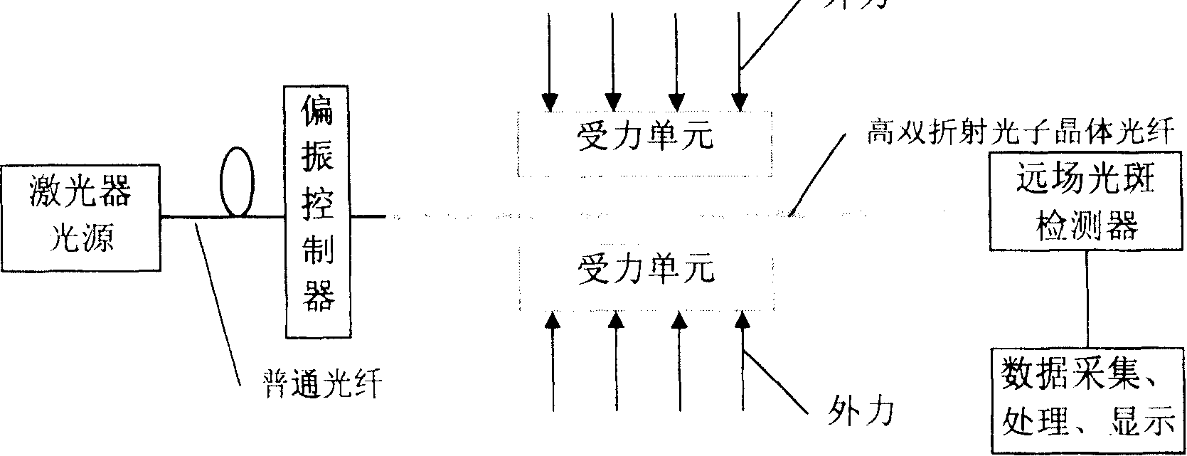
[0066] Embodiment 2; High birefringence dual-mode photonic crystal fiber transverse stress (strain) sensing system;
[0067] attached figure 2 As shown, the optical fiber in the figure is a high birefringence photonic crystal fiber, and the output light wavelength of the laser light source is 1310nm. The optical fiber at this wavelength is in a dual-mode working state, supporting fundamental mode and second-order even mode; In the detection area, after the polarization controller, only the fundamental mode and the second-order even mode of polarization in the y direction remain; the dislocation is coupled into the photonic crystal fiber, and after the dislocation displacement is adjusted, the power of the fundamental mode and the second-order even mode are nearly equal; Under the action of transverse stress, it passes through the optical fiber and outputs it to the far-field spot detector (which can be a high-sensitivity CCD array), and converts the spatial light intensity di...
Embodiment 3
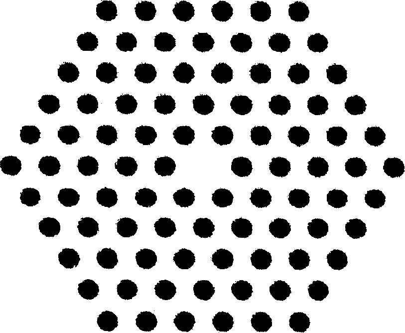
[0070] attached image 3 , 4 , 5 are three typical zero-birefringence dual-mode photonic crystal fibers, where the two polarization components of the fundamental mode (attached Figure 7 ) without birefringence, the second-order mode includes four approximately degenerate modes (attached Figure 8 ), the second-order mode transmitted in the actual fiber is composed of these four modes. Therefore, when transmitting in the fiber, the spot direction of the second-order mode rotates randomly. A polarization controller is added to the fiber input end to keep only light polarized in one direction transmitted in the fiber. In this way, only one component of the fundamental mode is transmitted, and only one polarization direction of light can be transmitted in the second-order mode, and the direction of the light spot is no longer rotated. A stable mode field can be formed.
[0071] The external force is applied to the transverse direction of the zero birefringence photonic crystal...
PUM
 Abstract
Description
Claims
Application Information
 - R&D
- Intellectual Property
- Life Sciences
- Materials
- Tech Scout
- Unparalleled Data Quality
- Higher Quality Content
- 60% Fewer Hallucinations
Browse by: Latest US Patents, China's latest patents, Technical Efficacy Thesaurus, Application Domain, Technology Topic, Popular Technical Reports.
© 2025 PatSnap. All rights reserved.Legal|Privacy policy|Modern Slavery Act Transparency Statement|Sitemap|About US| Contact US: help@patsnap.com


