Supercharge Your Innovation With Domain-Expert AI Agents!

Optical encoder

A technology of optical encoders and light sources, applied in the field of optical encoders, can solve problems such as errors, increased thickness of optical encoders, and non-compliance with miniaturization, and achieve the effect of increasing precision

Inactive Publication Date: 2008-06-25
LITE ON TECH CORP
View PDF7 Cites 0 Cited by
  • Summary
  • Abstract
  • Description
  • Claims
  • Application Information

AI Technical Summary

Problems solved by technology

However, this tends to increase the thickness of the optical encoder, which does not conform to the trend of miniaturization
Moreover, if there is dirt on the code wheel, it will still cause errors

Method used


Image

  • Optical encoder
  • Optical encoder
  • Optical encoder

Examples


Embodiment Construction

[0046] In order to have a further understanding of the purpose, structure, features, and functions of the present invention, the detailed description of the embodiments is as follows. The above descriptions about the content of the present invention and the following descriptions of the embodiments are used to demonstrate and explain the principle of the present invention, and to provide further explanation of the patent application scope of the present invention.

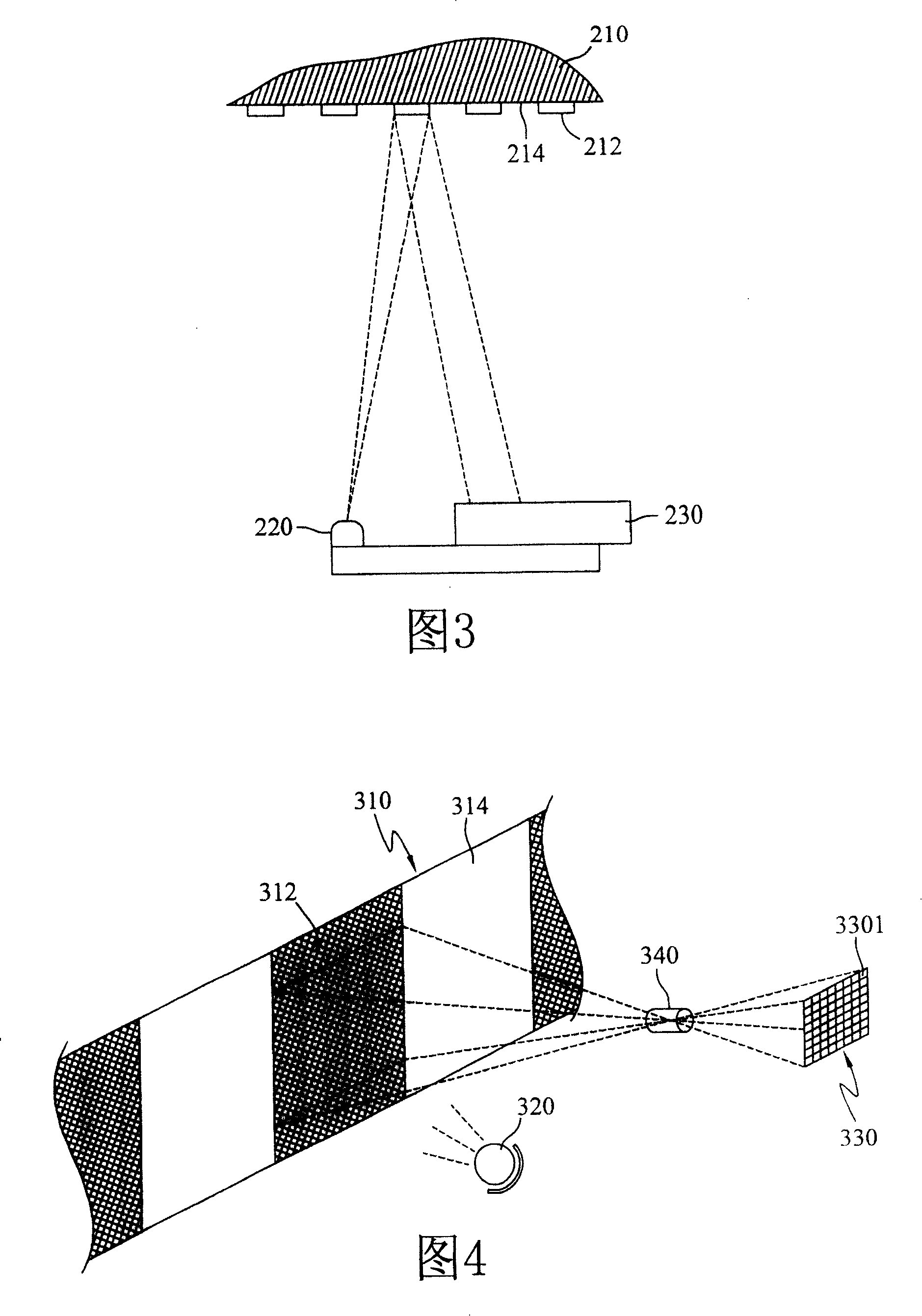
[0047] Please refer to FIG. 4 , which is a schematic structure diagram of an optical detector according to an embodiment of the present invention, which includes: a code strip 310 , a light source 320 , a light sensing component 330 and a first lens group (Lens) 340 .

[0048] Wherein, the code tape 310 is also driven by a wheel body (not shown in the figure) in response to the operation of the rotating device, and has reflective areas 312 and non-reflective areas 314 arranged alternately thereon. The code belt 310 c...


PUM


Abstract

This invention relates a optics encoder, which includes: a light source, which is to send ray; a code strap, which has the staggered reflecting area and non-reflecting area, wherein the reflection area is to reflect the ray of the light source; a first lens group, which is arranged at the same side of the code strap with the light source to gather the reflected ray from the reflecting area and send it out; and a light sensing group, which has a polarity of sensing cells that arrange as the matrix fashion, which is to receive the ray gathered from the fist lens group and transfer the received ray into the electric information to obtain a binary code combination, wherein the light sensing group and the code strap are all arranged at the two sides of the first lens group. This invention improves the feedback controlling precision through the eject errand of the light sensing group. Besides, for this light sensing group can be checked at many times, so it can improve the credibility of the measured information.

Description

technical field [0001] The invention relates to an optical encoder, in particular, the light sensing elements in the light sensing component are arranged in a matrix to improve precision and reliability. Background technique [0002] When it is desired to detect the position of a rotating device (such as a motor or mechanism shaft) or a high-speed moving device, it usually relies on optical or magnetic means to generate a binary identification corresponding to each position of the detected device through the opening or closing of the sensing component Codes, for example: several typical optical encoders are known in US Pat. [0003] These encoders mainly include: a light source for emitting a light beam; a code strip for modulating the light beam in response to the operation of a rotating device, such as a code wheel, an optical grating disk or an optical scale; and a photodetector for receiving and detecting the modulated light beam. Generally, some code tapes are provide...

Claims


Application Information

Patent Timeline
Patent Type & Authority Patents(China)
IPC IPC(8): G01D5/26
Inventor 魏智贤
Owner LITE ON TECH CORP
Features
  • R&D
  • Intellectual Property
  • Life Sciences
  • Materials
  • Tech Scout
  • Unparalleled Data Quality
  • Higher Quality Content
  • 60% Fewer Hallucinations
Learn More